Surface-distortion measuring device and method

a technology of surface distortion and measuring device, which is applied in the direction of refractive surface testing, instruments, image data processing, etc., can solve the problems of affecting the appearance of industrial products, causing the above-described distortion, and causing great damage to quality

Active Publication Date: 2011-01-11
JFE STEEL CORP +1
View PDF15 Cites 18 Cited by
  • Summary
  • Abstract
  • Description
  • Claims
  • Application Information

AI Technical Summary

Problems solved by technology

This considerably defaces the appearance of the industrial products and inflicts great damage on the quality thereof.
The above-described distortion is caused at any steps of performing a series of processing operations, such as press-forming, assembling, and coating of a metal plate.
During the press-forming, a surface of a press-formed product may deform due to the elastic deformation after the mold-releasing, and a distortion is possibly caused.
Additionally, when an extraneous matter, such as iron powder, attaches to a press die, a distortion may be caused on the press-formed product.
In addition, when a crack or a wrinkle is caused on a part of the press-formed product in the course of the press-forming, the tension of the product changes, which induces a distortion.
During the assembling, caulking or welding may cause a distortion.
During the coating, thermal deflection and coating unevenness due to baking, and attachment of an extraneous matter may cause a distortion.
However, it is extremely difficult to perform a quantitative shape measurement all over a surface of a target to measure the ruggedness of approximately 10 μm to 100 μm on the surface of the target of several hundreds millimeters to several meters in size.
However, the method takes a lot of time to perform the measurement, and is not a practical method.
However, techniques disclosed in Patent Documents 2 to 5 only visualize the distortion, and does not guarantee quantification of measured values.
In addition, in techniques disclosed in Patent Documents 6 to 8, the measurement result is likely to be affected by the light-and-shade of the projected stripe pattern or checker board pattern.
Additionally, an observable area is limited to an area near the edge of the light-and-shade portion of the pattern or a spatial resolution is limited due to averaging.
Accordingly, the limitation is imposed on the efficiency.
Furthermore, in a technique disclosed in Patent Document 9, a problem remains in that a time required for measurement is long since a mirror image is scanned with one slit and in that quantitative evaluation equation between the timing lags and the degree of surface distortion is not established.
However, it is impossible to perform quantitative measurement of surface-distortion distribution equivalent to small ruggedness of approximately several tens micrometers on a specular surface or semi-specular surface, such as, for example, a surface of a vehicle outer panel.
In addition, when inspection of surface quality-defects resulting from a surface distortion is performed in each of metal-plate processing steps of performing at least one of press-forming, component mounting, assembling, coating, heat treatment, and inspection of a finished product, it is necessary to inspect the product moving on the manufacturing line at a high-speed.
However, conventional techniques cannot cope with the speed of product moving on the manufacturing line, and it is impossible to perform inline inspection.

Method used


Image

  • Surface-distortion measuring device and method
  • Surface-distortion measuring device and method
  • Surface-distortion measuring device and method

Examples


Embodiment Construction

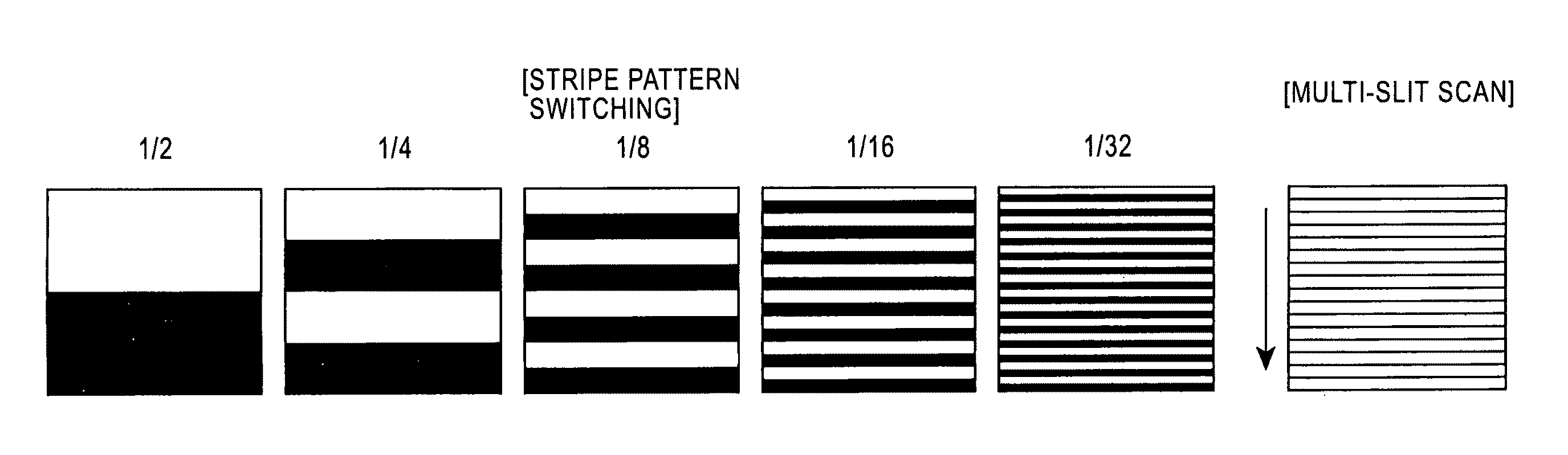
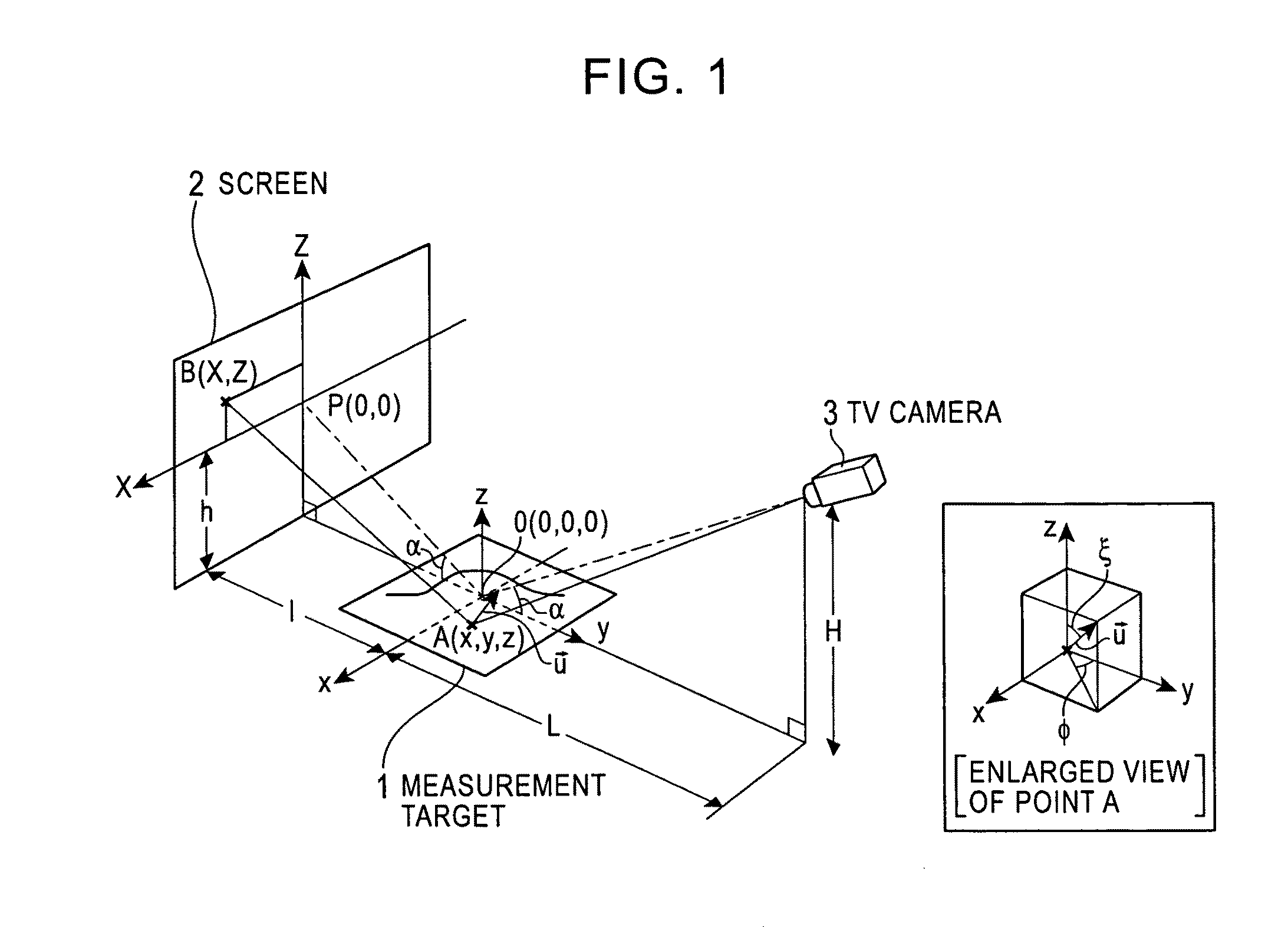
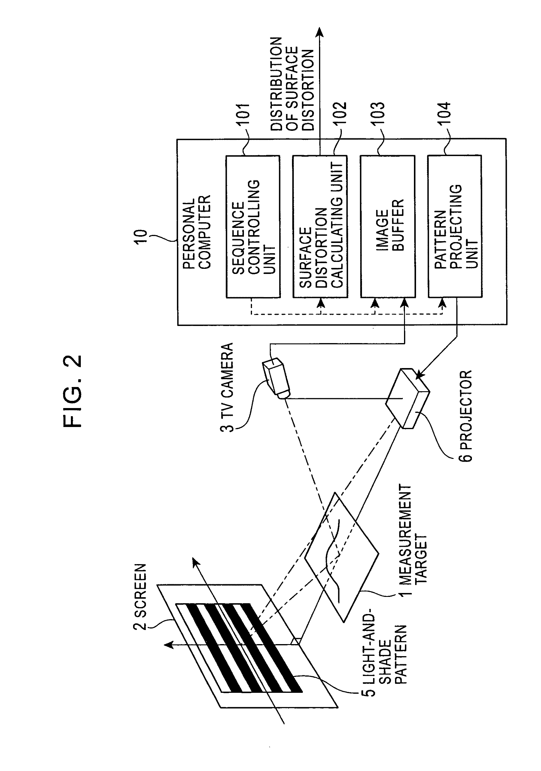
[0071]The present invention utilizes a phenomenon that a light-and-shade pattern reflected in a specular or semi-specular measurement-target surface is distorted due to a surface distortion. Patterns of a plurality of light-and-shade patterns displayed on pattern displaying means (for example, a screen) reflected in a measurement-target surface, namely, mirror images of the plurality of light-and-shade patterns reflected in the measurement-target surface, are captured using capturing means (for example, a television (TV) camera). Image processing is performing on the captured images, and coordinates of a point on the pattern displaying means (a display surface thereof) corresponding to each point on the measurement-target surface are determined. The degree of surface distortion is calculated on the basis of a measurement principle described below. Furthermore, surface-distortion distribution is determined by performing this calculation for every observable point on the measurement-t...


PUM


Abstract

A surface-distortion measuring device and a surface-distortion measuring method can quantitatively, rapidly, and highly accurately measure and evaluate surface-distortion distribution at all of observable points on a specular or semi-specular surface of a measurement target. The device includes pattern displaying means 2 capable of switching and displaying a plurality of kinds of light-and-shade patterns 5, capturing means 3 for capturing mirror images, reflected in the specular or semi-specular surface of a measurement target 1, of the plurality of light-and-shade patterns displayed on the pattern displaying means, and surface-distortion distribution calculating means 10 for performing image processing on the captured mirror images of the plurality of light-and-shade patterns to calculate surface-distortion distribution of the measurement-target surface.

Description

TECHNICAL FIELD[0001]The present invention relates to surface-distortion measuring devices and surface-distortion measuring methods. More specifically, the present invention relates to surface-distortion measuring devices and surface-distortion measuring methods for quantitatively measuring and evaluating surface-distortion distribution at all observable points on a specular or semi-specular surface of a measurement target using optical means.BACKGROUND ART[0002]If a wavy distortion, so-called “surface distortion”, exists on a surface of industrial products having specular or semi-specular surfaces, such as press-formed and coated vehicle outer panels, coated architectural wall panels, or flat glass mirrors, a reflected background image looks significantly distorted due to the principle of “optical lever” no matter how small the distortion is. This considerably defaces the appearance of the industrial products and inflicts great damage on the quality thereof.[0003]The above-describe...

Claims


Application Information

Patent Timeline
Patent Type & Authority Patents(United States)
IPC IPC(8): G01B11/24
CPCG01B11/2536G01M11/005G01B11/2531G06T7/0057G01B11/2527G01N21/8806G06T7/521G01B11/25G01B11/00
Inventor SATO, KENTAROSAITO, TAKANOBUIWAMA, TAKASHIYOSHITAKE, AKIHIDEUESUGI, MITSUAKI
Owner JFE STEEL CORP
Why Eureka
Try Eureka