
Tapered roller bearing, tapered roller bearing apparatus, and automotive pinion shaft supporting apparatus utilizing same tapered roller bearing apparatus

a tapered roller bearing and tapered roller bearing technology, which is applied in the direction of roller bearings, mechanical equipment, roller bearings, etc., can solve the problems of large running torque of tapered roller bearings, loss, and no attempt to control the amount of crownings, so as to reduce the running torque

Active Publication Date: 2011-01-18
JTEKT CORP
View PDF21 Cites 12 Cited by
  • Summary
  • Abstract
  • Description
  • Claims
  • Application Information

AI Technical Summary

Benefits of technology

[0041]According to the tapered roller bearing, the tapered roller bearing apparatus and the automotive pinion shaft supporting apparatus which utilizes the tapered roller bearing apparatus, even in the event that the roller diameter is increased, the running torque can be reduced in the low rotational speed range.

Problems solved by technology

However, since the tapered roller bearings also have a drawback of a large running torque (loss), techniques in which raceways of inner and outer rings and rolling contact surfaces of tapered rollers are crowned to reduce the rolling friction (refer to, for example, Patent Document Nos. 1 to 2) have been proposed.
However, no attempt had been made to control the amounts of crownings so as to reduce the running torque of a tapered roller bearing by paying attention to an idea in which crowning is taken as quantity.
On the other hand, while one of main causes of the generation of running torque in a tapered roller bearing in a differential is the rolling viscous resistance of tapered rollers and the agitation loss of oil, there had been provided no clear guideline on how to reduce them.

Method used


Image

  • Tapered roller bearing, tapered roller bearing apparatus, and automotive pinion shaft supporting apparatus utilizing same tapered roller bearing apparatus
  • Tapered roller bearing, tapered roller bearing apparatus, and automotive pinion shaft supporting apparatus utilizing same tapered roller bearing apparatus
  • Tapered roller bearing, tapered roller bearing apparatus, and automotive pinion shaft supporting apparatus utilizing same tapered roller bearing apparatus

Examples


Embodiment Construction

[0058]Hereinafter, a tapered roller bearing, a tapered roller bearing apparatus and an automotive pinion shaft supporting apparatus according to an embodiment of the invention will be described in detail by reference to the accompanying drawings.

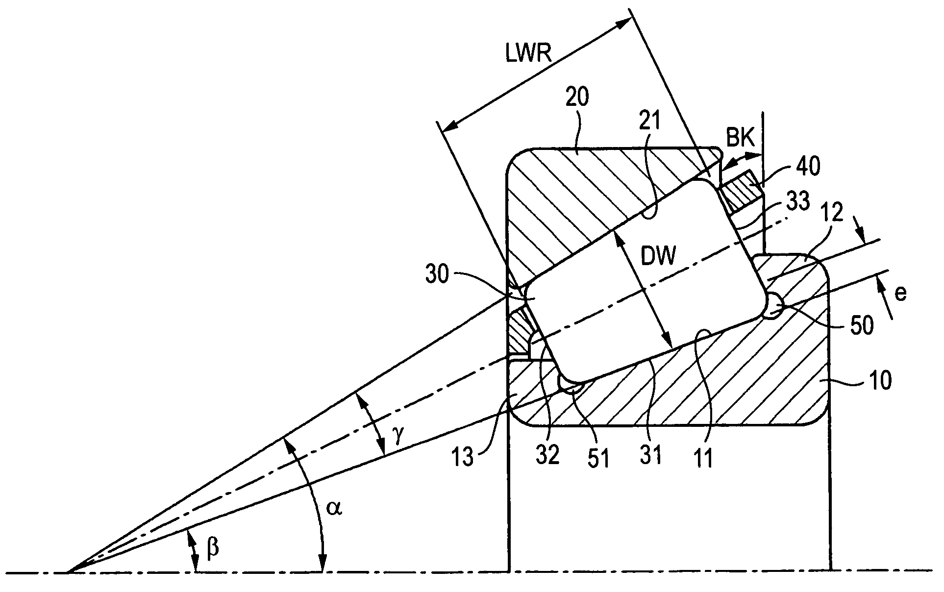
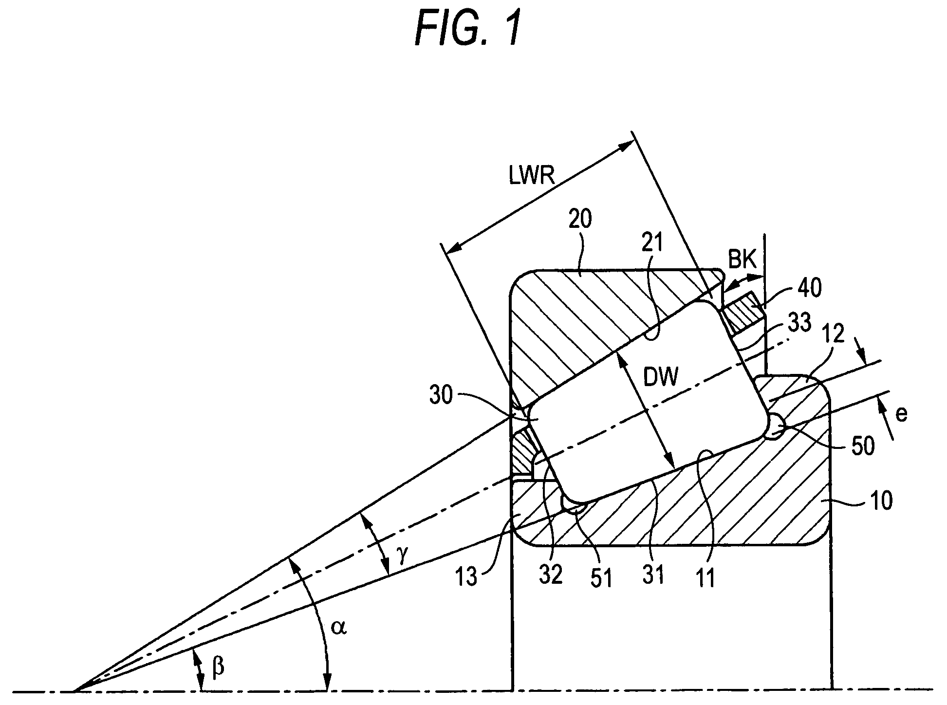
[0059]FIG. 1 is an axial sectional view of a tapered roller bearing according to an embodiment of the invention. This tapered roller bearing is used on a pinion gear side of an automotive differential as an automotive pinion shaft supporting apparatus and includes an inner ring 10 in which an inner ring raceway surface 11 made up of a coned surface is formed on an outer circumference thereof, an outer ring 20 in which an outer ring raceway surface 21 made up of a coned surface is formed on an inner circumference thereof, a plurality of tapered rollers 30 interposed between the inner and outer rings and each having a rolling contact surface 31 which is made up of a coned surface and is formed on an outer circumference thereof, and a case 40 f...


PUM


Abstract

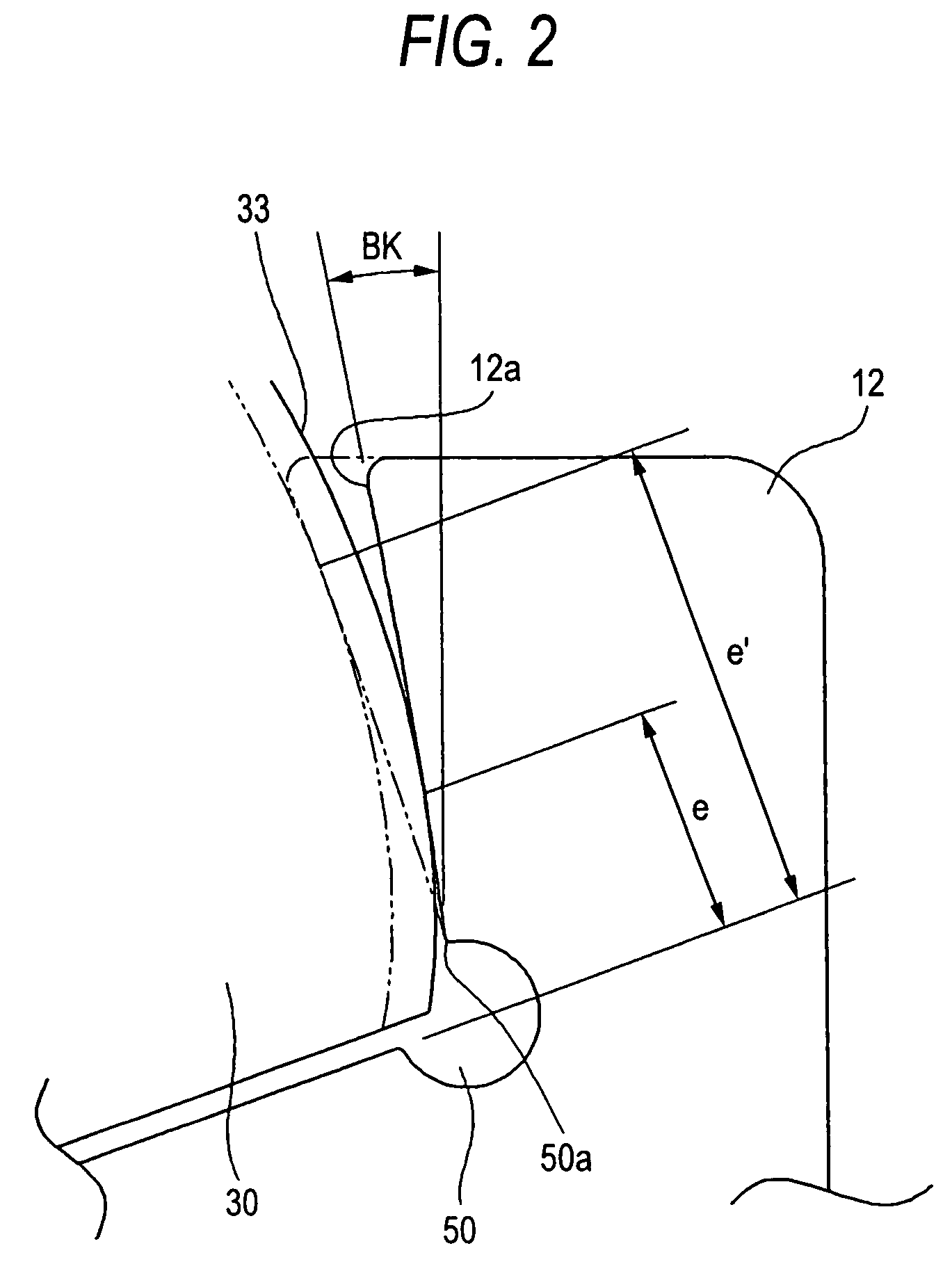
In a tapered roller bearing, LWR / DW is in the range of 1.1 to 1.7 where LWR represents a roller effective length of tapered rollers and DW represents a roller mean diameter of tapered rollers. RCO / LRO is 30 to 150, and RCI / LRI is 50 to 260 where RCO represents a crowning radius of an outer ring, LRO represents a raceway length of the outer ring, RCI represents a crowning radius of an inner ring and LRI represents a raceway length of the inner ring. The following expressions are satisfied: 20°≦α≦30°, and α−0.87γ−0.334≦BK≦α−0.87γ−0.167, where α represents a raceway angle of the outer ring, γ represents a roller angle of the tapered rollers, and BK represents a rib angle of a large rib portion of the inner ring.

Description

BACKGROUND OF THE INVENTION[0001]The present invention relates to a tapered roller bearing which is used in differentials for motor vehicles and industrial machines, a tapered roller bearing apparatus which utilizes the tapered roller bearing and an automotive pinion shaft supporting apparatus which utilizes the tapered roller bearing apparatus.[0002]Since tapered roller bearings are characterized in that they have a high load capacity and a high rigidity, compared to ball bearings, the tapered roller bearings are used in automotive pinion shaft supporting apparatuses in differentials and transaxles of motor vehicles. However, since the tapered roller bearings also have a drawback of a large running torque (loss), techniques in which raceways of inner and outer rings and rolling contact surfaces of tapered rollers are crowned to reduce the rolling friction (refer to, for example, Patent Document Nos. 1 to 2) have been proposed.[0003]In the tapered roller bearings described Patent Do...

Claims


Application Information

Patent Timeline
Patent Type & Authority Patents(United States)
IPC IPC(8): F16C19/36F16H57/04
CPCF16C19/364F16C23/088F16C33/36F16C33/585F16C33/6674Y10T74/19693F16C2240/40F16C2240/50F16C19/225F16C33/366F16C2240/30F16C2240/34F16C2240/70F16C2361/61
Inventor OHSHIMA, HIROYUKITODA, KAZUTOSHIMATSUYAMA, HIROKIKAWAGUCHI, KOUJIMASUDA, NAOKI
Owner JTEKT CORP
Learn More