
Balanced amplifying device having a bypass branch

a technology of balanced amplifying device and bypass branch, which is applied in the direction of gated amplifiers, amplifiers, semiconductor devices/discharge tubes, etc., can solve the problems of increased insertion loss, limiting the performance of switches, and always controversial implementation of switches at the input of amplifiers, so as to achieve positive influence on losses

Active Publication Date: 2011-01-18
TELEFON AB LM ERICSSON (PUBL)
View PDF8 Cites 1 Cited by
  • Summary
  • Abstract
  • Description
  • Claims
  • Application Information

AI Technical Summary

Benefits of technology

The present invention is about an improved balanced amplifying device with a bypass branch. The device has a signal bypass branch that can be connected to an electrical termination element and an amplifying section. The device has two coupling / splitting units that can combine signals from the two amplifiers and provide them as output signals. The bypass branch is connected to the second port of the first coupling unit and the input of the second amplifier. The device can be used in a wireless access point and has advantages such as amplifying weaker signals and improving loss performance.

Problems solved by technology

In all these cases the performance of the switches is the limiting factor.
The implementation of a switch at the input of the amplifier is always controversial in terms of additional insertion loss, possible stability problems and MTBF (Mean Time Between Failure).
The other problem is the required high reverse isolation of the switches that is needed to ensure stability (self oscillation immunity) of the amplifying device.
The choice of the possible switches that can be used is limited by the fact that in the bypass mode no power supply is available.
The above mentioned problems are highly undesirable, since in normal mode the amplifier should be as good as possible.
This means that this safety measure does impose limitations on the efficiency of the amplifier.

Method used


Image

  • Balanced amplifying device having a bypass branch
  • Balanced amplifying device having a bypass branch
  • Balanced amplifying device having a bypass branch

Examples


first embodiment

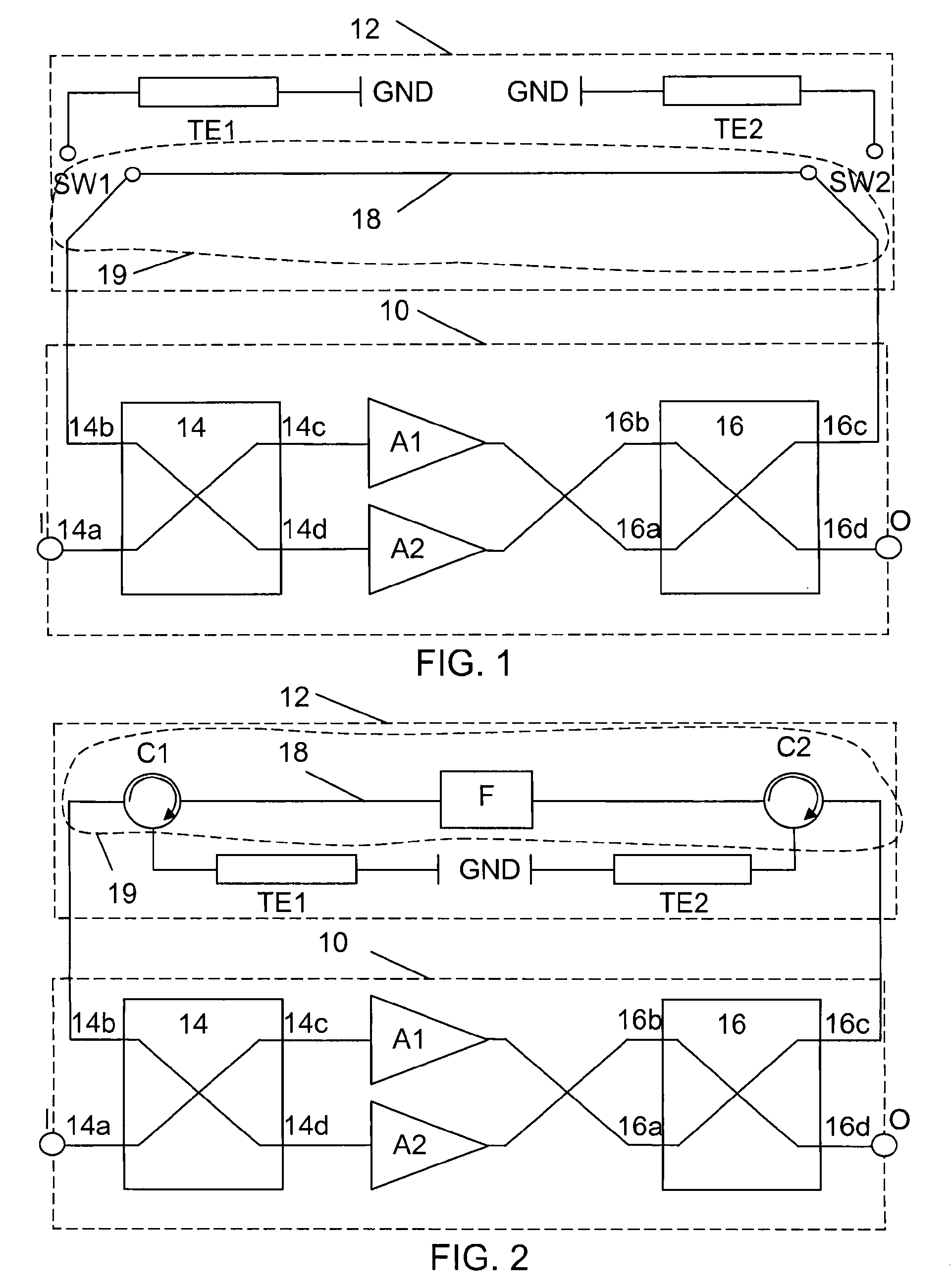
[0034]a balanced amplifying device is shown in a circuit diagram in FIG. 1. The balanced amplifying device, which is a low noise amplifier, includes an amplifying section 10 and a bypass and isolating section 12, both shown as dashed boxes. The amplifying section 10 includes a first coupling / splitting unit 14 in the form of an input hybrid coupler 14. The input hybrid coupler 14 has four ports, where a first port 14a acts as an input port and also as the input I of the amplifying device, a second port 14b acts as an isolated port in normal mode and is therefore connected to the bypass and isolating section 12. A third port 14c of the input hybrid coupler 14 is connected to the input of a first amplifier A1, while a fourth port 14d of the input hybrid coupler 14 is connected to the input of a second amplifier A2. The amplifiers A1 and A2 include necessary matching and biasing (not shown) and are provided with power (also not shown). The output of the first amplifier A1 is connected t...

second embodiment

[0045]This second embodiment has a number of advantages. The design requires no switches at all and the bypass section has no active components, which means that bypass operation may be provided even if there is no power. Since there are no active components, the solution is robust and confident with good LTBF (life time between failures).

[0046]Also this second embodiment may be varied. It can include more circulators in order to provide further reverse isolation. It may also include fewer circulators. In its simplest form it only includes one circulator. It should also be realised that the filter may be omitted.

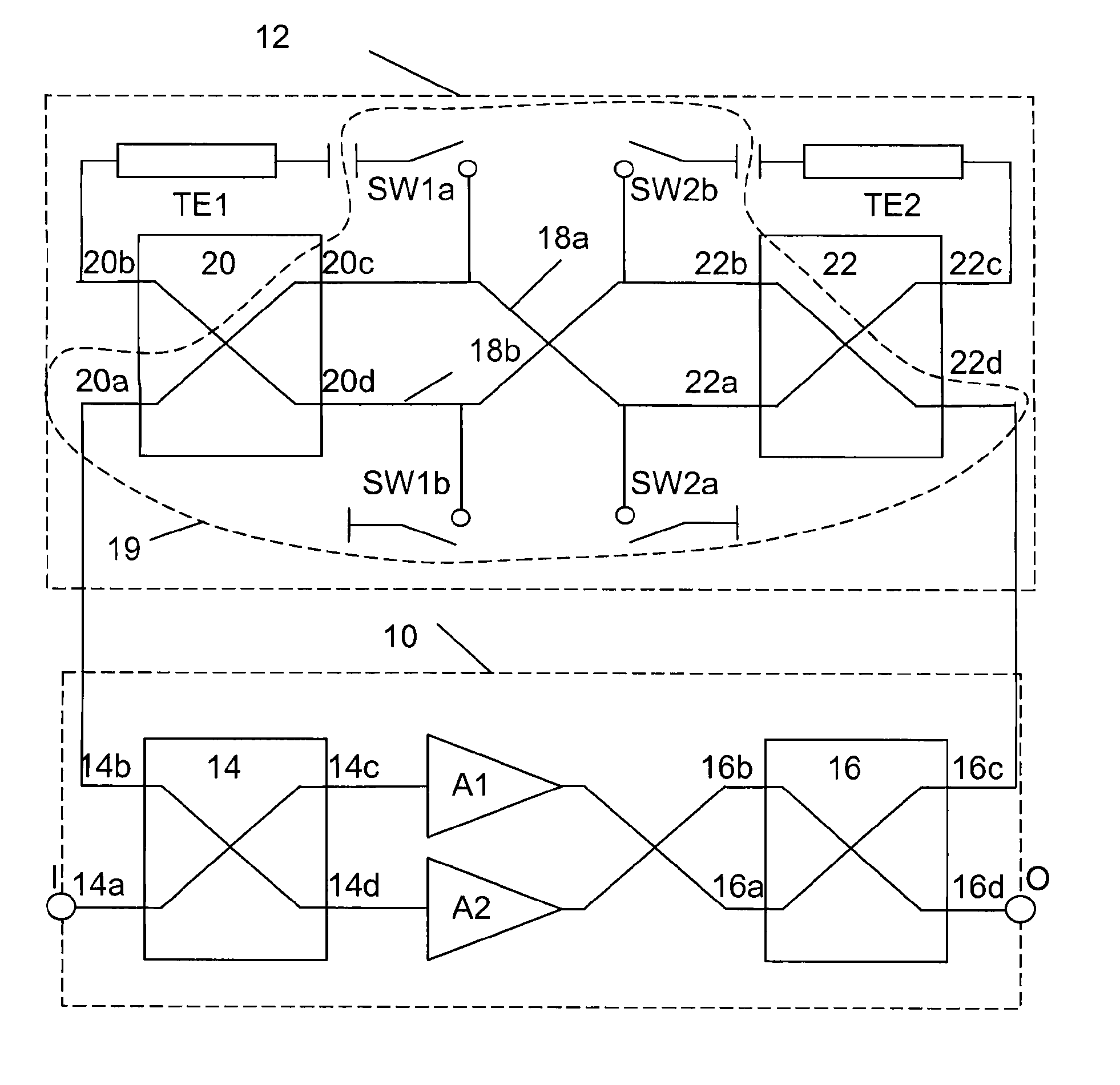
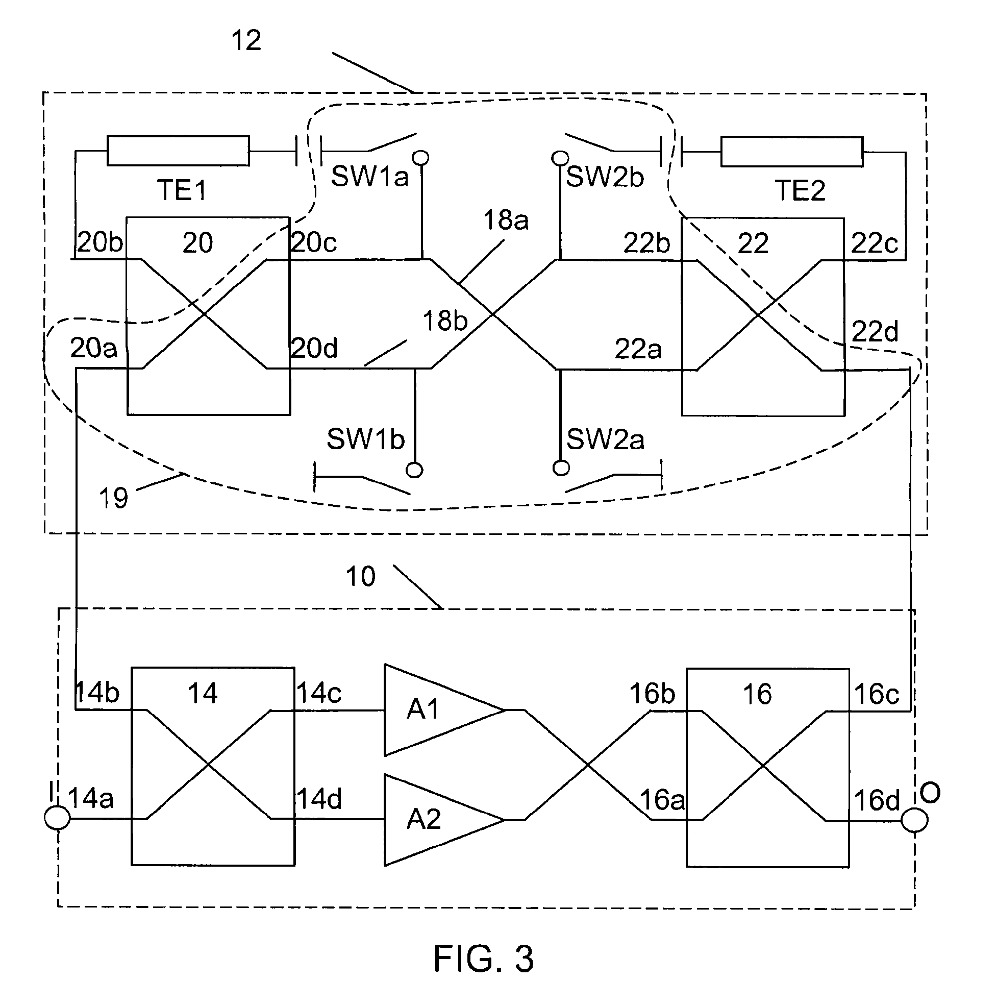
[0047]FIG. 3 shows a circuit diagram of a balanced amplifying device according to a third embodiment of the present invention. The amplifying section 10 of this third embodiment is identical to the amplifying section of the first embodiment. Here only the bypass and isolating section 12 differs. In this embodiment the isolation is again provided through a first and second te...

fourth embodiment

[0051]The advantage of this fourth embodiment is that it improves the nonlinear performance of the balanced amplifying device in the bypass mode.

[0052]There are a number of variations that are possible also with the third and fourth embodiments. The bypass switches may be connected in either of the two described ways in both embodiments. One pair of bypass switches may also be omitted, and then preferably the output bypass switches. The fourth port of the second bypass hybrid coupler may be connected to the fourth port of the output hybrid coupler. However, in this case the second termination element will be connected to the third port of the output hybrid coupler and a further termination element be connected between the third port of the second bypass hybrid coupler and ground. The performance enhancement switches of the fourth embodiment may also be connected in the same way as the bypass switches in the third embodiment. The performance enhancement switches may furthermore be in...


PUM


Abstract

A balanced amplifier includes a bypass branch (19), termination elements (TE1, TE2) and an amplifying section (10). The section (10) includes amplifiers (A1, A2), first coupling / splitting unit (14) having a first input signal receiving port (14a), a second port (14b) connected to a termination element (TE1), a third port (14c) connected to a first amplifier (A1), and a fourth port (14d) connected to a second amplifier (A2). The section (10) also includes second coupling / splitting unit (16) having a first port (16a) connected to first amplifier (A1), a second port (16b) connected to second amplifier (A2) and a third port (16c) connected to a termination element (TE2). The second coupling / splitting unit (16) combines signals from amplifiers (A1, A2) as output signals on a fourth port (16d) for supply to a signal output (O). The branch (18) is connected to the second port (14b) of the first coupling / splitting unit (14) and provides bypass signals to output (O).

Description

TECHNICAL FIELD OF THE INVENTION[0001]The present invention relates to the field of balanced amplifying devices and more particularly to a balanced amplifying device configured to operate in normal and bypass modes as well as to a wireless access point for a wireless network including such a balanced amplifying device.DESCRIPTION OF RELATED ART[0002]One often used low noise amplifier in the field of wireless communication is a so-called balanced low noise amplifier, which is often used in base stations. Such an amplifier is then often made up of a first coupling / splitting unit having four ports, where a first port receives an input signal from an antenna, a second port is connected to an electrical termination element, a third port is connected to the input of a first amplifier, and a fourth port is connected to the input of a second amplifier. The output of the first amplifier is here connected to a first port of a second coupling / splitting unit and the output of the second amplifi...

Claims


Application Information

Patent Timeline
Patent Type & Authority Patents(United States)
IPC IPC(8): H03F3/68
CPCH03F1/0277H03F3/602H03F3/72H03F2200/192H03F2200/198H03F2200/204H03F2203/7227H03F2203/7239
Inventor PLOTKA, ANDRZEJ
Owner TELEFON AB LM ERICSSON (PUBL)
Learn More