

Dispensing support device and dispensing support method
a technology of support device and support device, which is applied in the direction of supporting apparatus, instruments, de-stacking articles, etc., can solve the problems of high price, high cost, and inability to take any action, so as to reliably prevent the wrong dosage of drugs, simple configuration, and low cost
- Summary
- Abstract
- Description
- Claims
- Application Information
AI Technical Summary
Benefits of technology
Problems solved by technology
Method used
Image

Examples
first embodiment
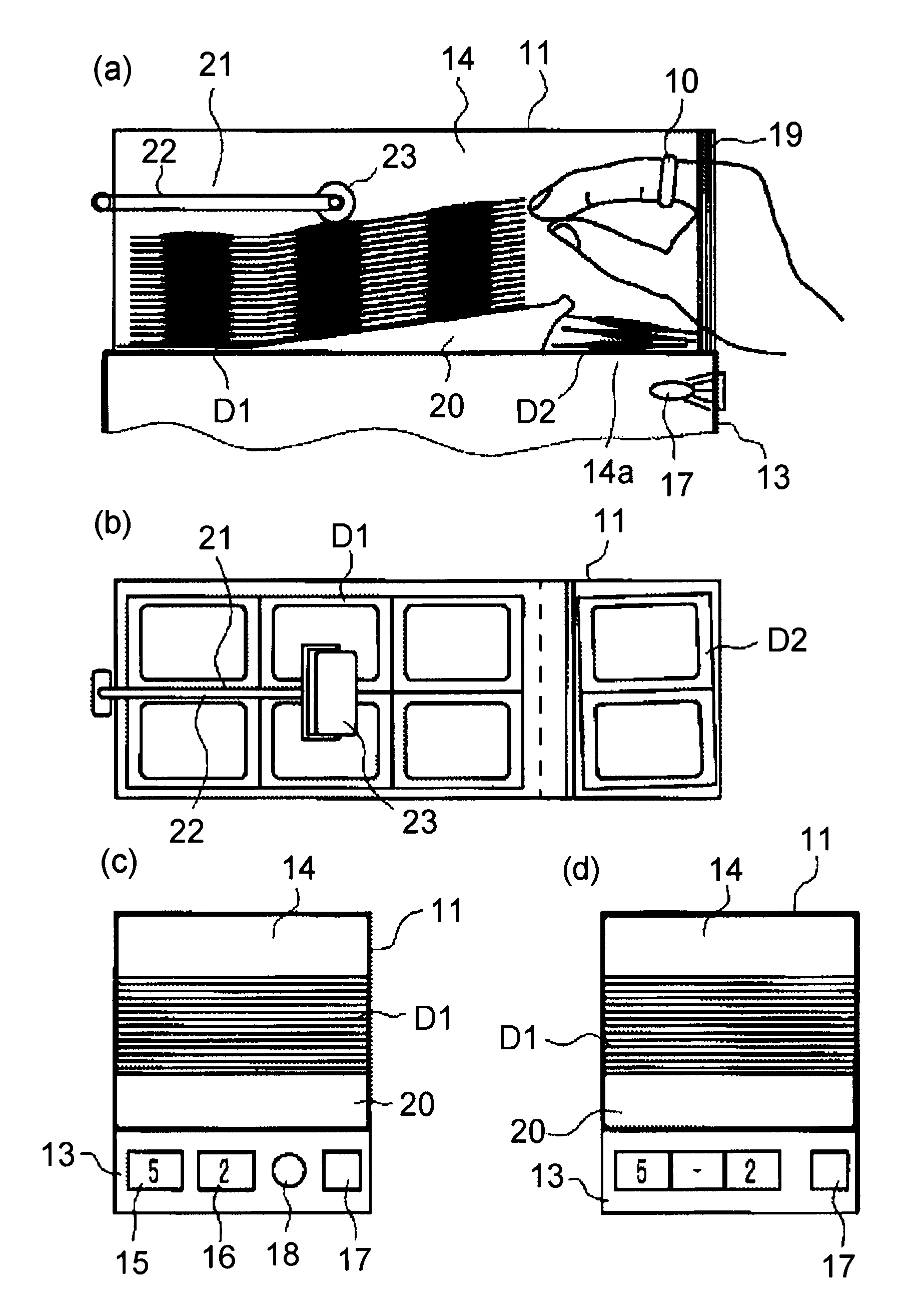
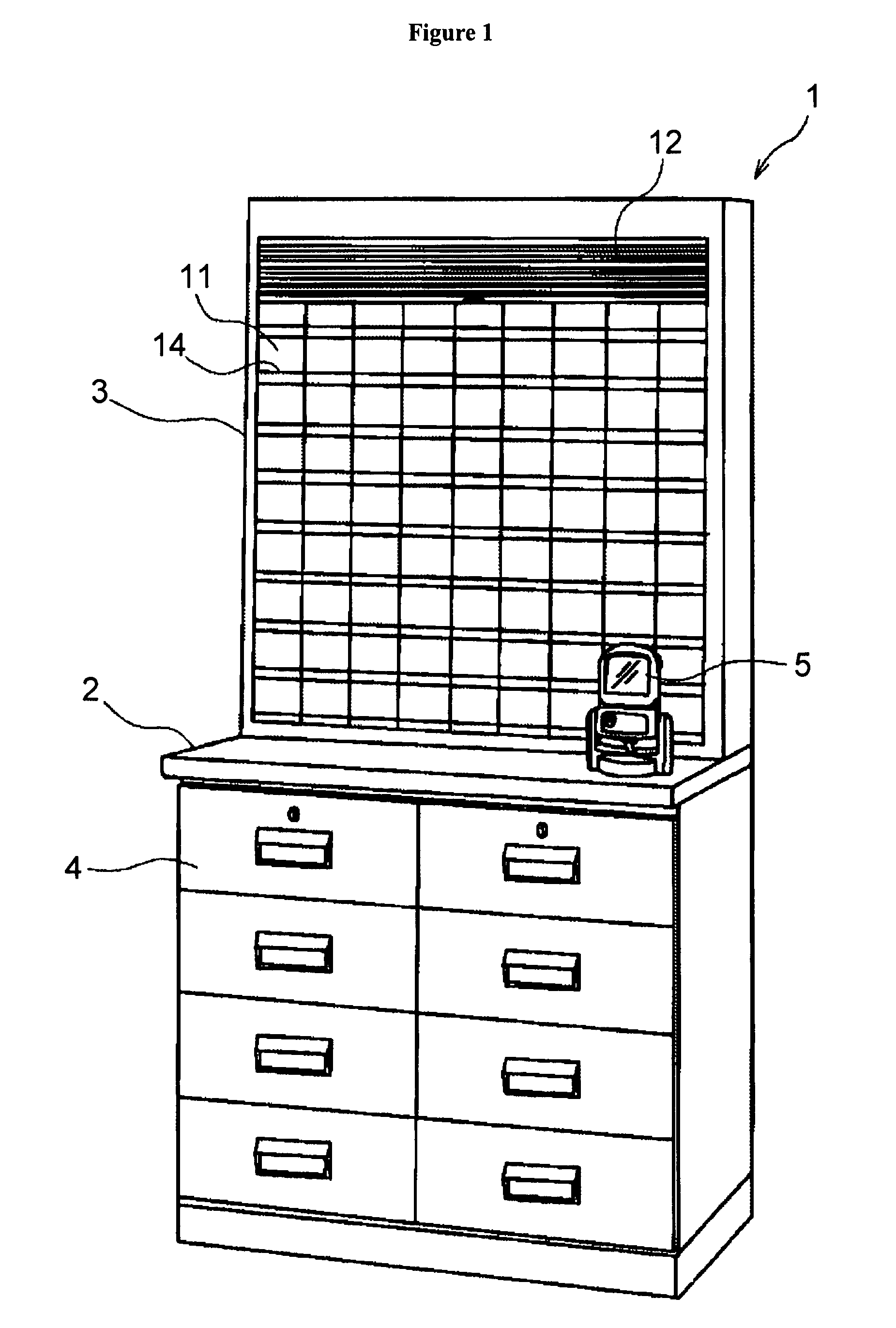
[0039]FIG. 1 shows the exterior of a dispensing support device 1 according to a first embodiment. This dispensing support device 1 is formed by placing a drug rack 3 on a dispensing base 2.
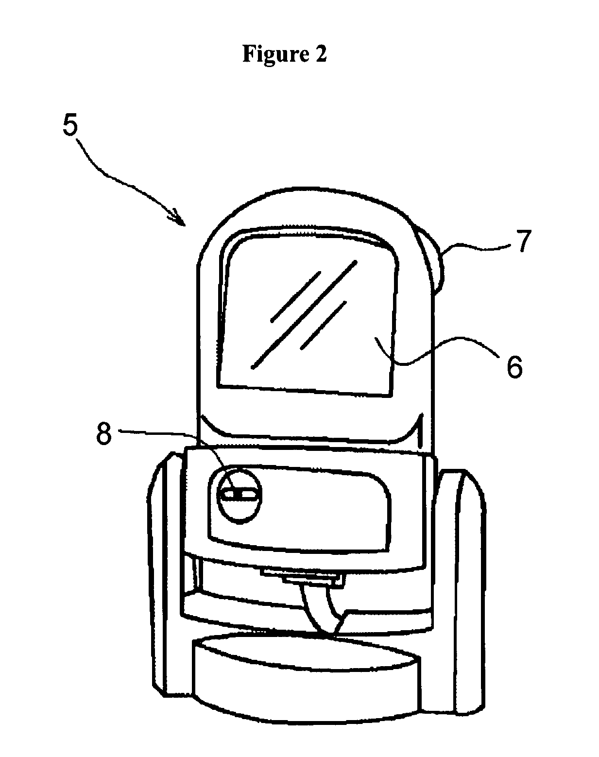
[0040]The dispensing base 2 includes a plurality of drawers 4 drawably provided in a front side thereof, and has health related members such as catheter, poultices, gauze, or the like, and drugs such as guttae or the like, which are contained inside thereof. In addition, on the dispensing base 2, a bar code reader 5 shown in FIG. 2 is set. This bar code reader 5 includes a bar code identification part 6, a RFID antenna 7 (RFID: Radio Frequency Identification), a buzzer 8, and the like. The bar code identification part 6 identifies a bar code A printed on a dispensing direction note P (see FIG. 8), whereby prescription data for a patient written on a direction note P is extracted from among those inputted from a host computer 9 (data concerning contents of prescriptions created by a doctor). The RF...
second embodiment
[0067]FIGS. 18 and 19 show a dispensing support device 30 according to a second embodiment. This dispensing support device 30 differs from the one according to the first embodiment mainly in the following point. Hereinafter, in the description and figures below, those portions configured in the same manner are provided with the same numerals and thus omitted from the description.
[0068]In each cassette 11 of the drug rack 3, an approaching object detection sensor 31 is provided as shown in FIG. 20. In addition, in each cassette 11, a first display part 32 is provided as shown in FIG. 21. Further, also in each drawers 4, a second display part 33 is provided on the center of the holding part 4b provided on the front surface and a third display part 34 is provided on the top surface of a partition wall 4a inside the drawers 4, as shown in FIGS. 22 through 24.
[0069]Moreover, below the drug rack 3, a key hole 35 is provided which permits insertion of a shutter open-close key, not shown. T...
PUM
 Abstract
Description
Claims
Application Information