
SSD test systems and methods

a test system and solid state drive technology, applied in the direction of digital storage, instruments, measurement devices, etc., can solve the problems of testing platforms not being able to locate where, test platforms cannot control data programming to which sector/page/block of ssd,

Inactive Publication Date: 2011-01-18
SUPER TALENT TECH CORP
View PDF3 Cites 75 Cited by
  • Summary
  • Abstract
  • Description
  • Claims
  • Application Information

AI Technical Summary

Benefits of technology

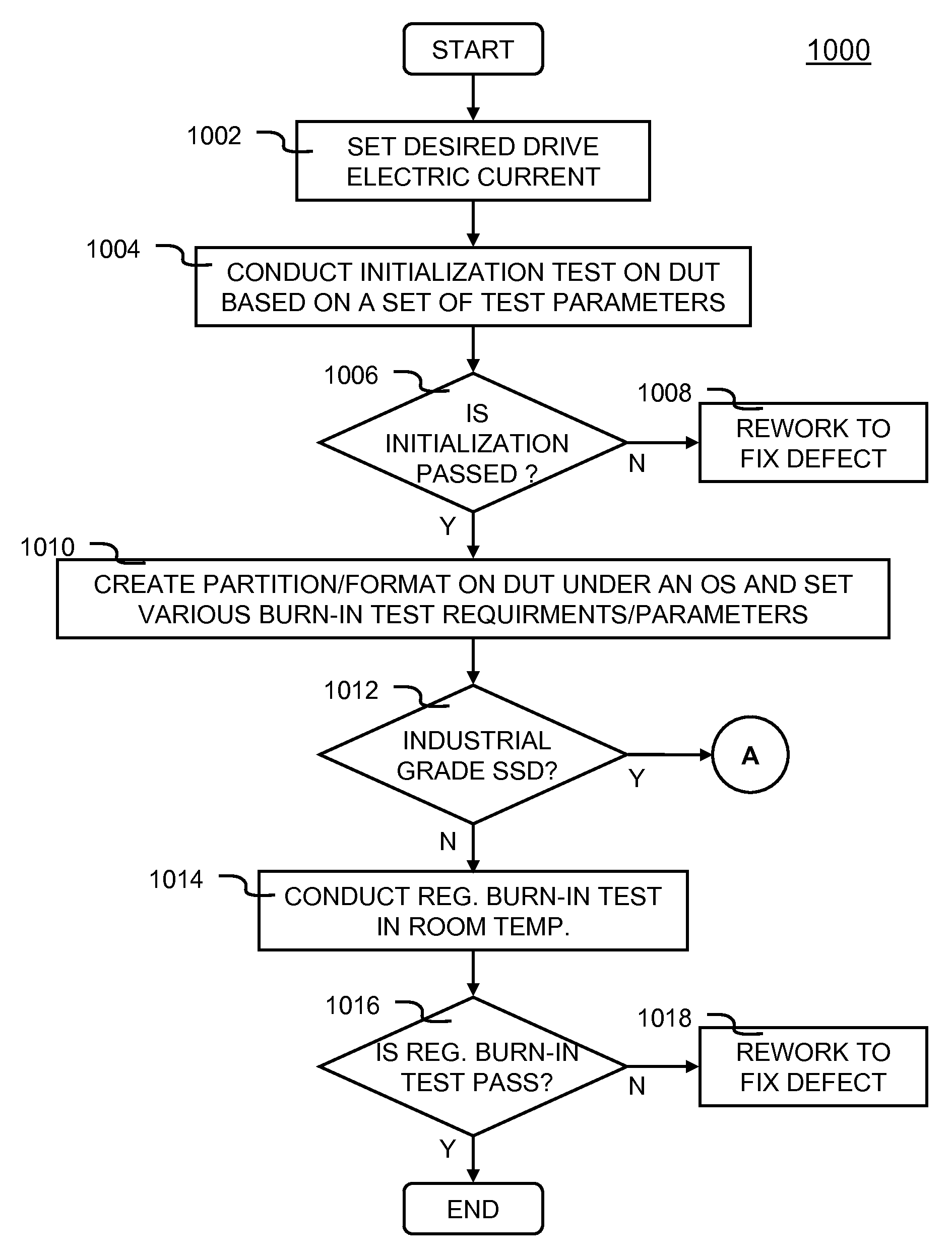
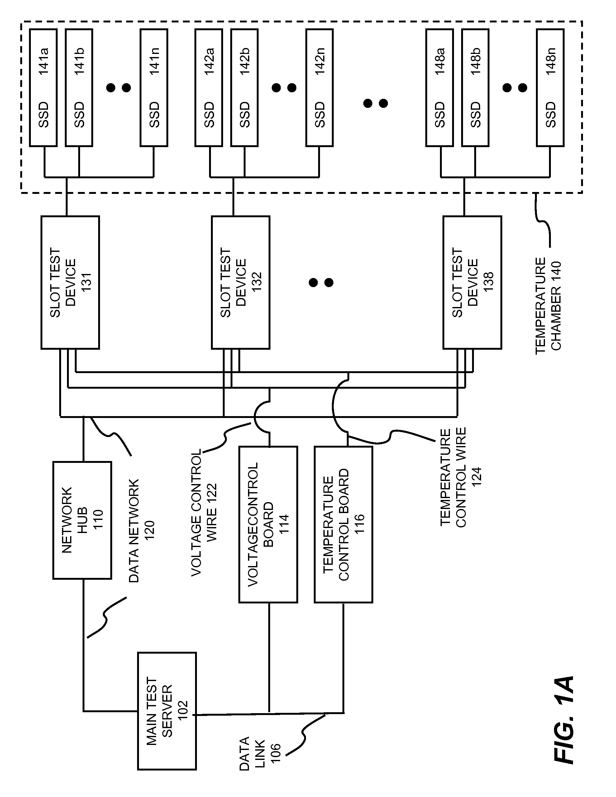
[0020]According to another aspect, testing the random power shut off is achieved with the main test server controlling a verifiable and reproducible random delay to embark a power cycle operation (i.e., turn electric power off and then on) while the SSD is under continuous data programming operations. In order to pass the power on / off test, the SSD under test must be able to recover all of the data written before the power cycle occurred. This can be achieved by checking whether critical area of the SSD (e.g., File Allocation Table (FAT)) is intact after a fixed time delay after the power cycle. The fixed time delay allows the SSD to initialize or start up (e.g., boot up).

Problems solved by technology

Since wear leveling and logical-to-physical mapping schemes dictate flash memory data programming or writing order, the test platform cannot control data programming to which sector / page / block of the SSD.
As a result, test platform cannot locate where the problem flash memory when the SSD controller controls the SSD.

Method used


Image

  • SSD test systems and methods
  • SSD test systems and methods
  • SSD test systems and methods

Examples


Embodiment Construction

[0046]In the following description, numerous details are set forth to provide a more thorough explanation of embodiments of the present invention. It will be apparent, however, to one skilled in the art, that embodiments of the present invention may be practiced without these specific details. In other instances, well-known structures and devices are shown in block diagram form, rather than in detail, in order to avoid obscuring embodiments of the present invention.

[0047]Reference herein to “one embodiment” or “an embodiment” means that a particular feature, structure, or characteristic described in connection with the embodiment can be included in at least one embodiment of the invention. The appearances of the phrase “in one embodiment” in various places in the specification are not necessarily all referring to the same embodiment, nor are separate or alternative embodiments mutually exclusive of other embodiments. Further, the order of blocks in process flowcharts or diagrams rep...


PUM


Abstract

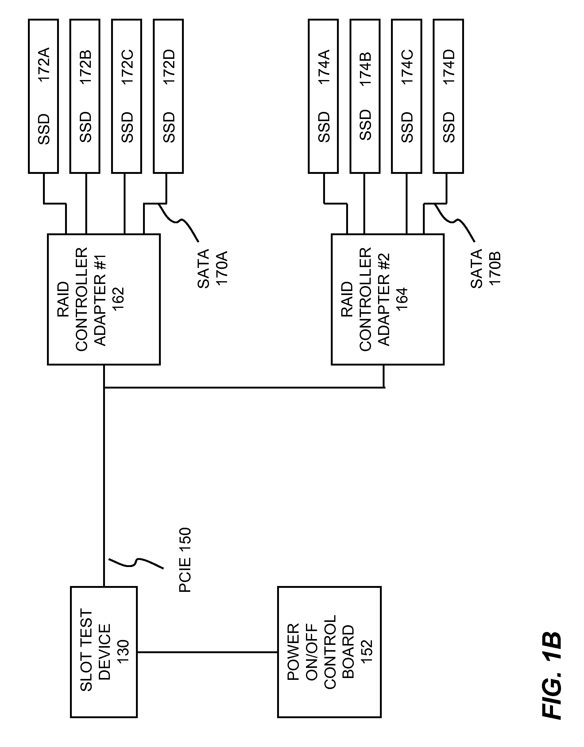
Solid state drive (SSD) testing processes and methods are disclosed. In one embodiment, the SSD testing process comprises: specifying a set of test parameters of firmware, operating system and flash memory for a plurality of SSDs under test (DUTs) in an SSD test system, the set of test parameters includes a model number, a serial number, a desired defective or bad block ratio and a size of the firmware, wherein the model and serial number are configured onto each of the DUTs; performing an initialization test of all of the DUTs based on the specified test parameters to determine a pre-qualified group of the DUTs that passed the initialization test; conducting at least one level of burn-in test for each SSD in the pre-qualified group; conducting at least one level of burn-in test for each SSD in the pre-qualified group; and assigning a quality grade to said each SSD based on which level of the at least one level of burn-in test said each SSD has been tested and passed, wherein the quality grade includes a commercial grade SSD made using at least one Multi-Level Cell flash memory.

Description

CROSS-REFERENCE TO RELATED APPLICATIONS[0001]This application is a continuation-in-part (CIP) of U.S. Patent Application for “Non-Volatile Memory Device Manufacturing Process Testing Systems and Methods Thereof”, Ser. No. 12 / 042,316, filed on Mar. 4, 2008, now U.S. Pat. No. 7,802,155.[0002]This application is also a CIP of U.S. Patent Application for “High Volume Testing for USB Electric Data Flash Cards”, Ser. No. 11 / 626,347, filed on Jan. 23, 2007, now U.S. Pat. No. 7,702,984.[0003]This application is also a CIP of U.S. Patent Application for “System and Method for Producing High Volume Flash Memory Cards”, Ser. No. 11 / 979,102, filed on Oct. 31, 2007, now abandoned.[0004]This application is also a CIP of co-pending U.S. Patent Application for “Methods and Systems for Managing Memory Addresses in A Large Capacity Multi-level Cell (MLC) Based Flash Memory Device”, Ser. No. 12 / 025,706, filed on Feb. 4, 2008.[0005]This application is also a CIP of U.S. Patent Application for “Flash me...

Claims


Application Information

Patent Timeline
Patent Type & Authority Patents(United States)
IPC IPC(8): G01R31/28G11C16/04
CPCG11C29/08G11C29/56G11C5/04G11C16/04
Inventor SHIN, MYEONGJINLEE, CHARLES C.YU, I-KANGMA, ABRAHAM CHIH-KANG
Owner SUPER TALENT TECH CORP
Learn More