Heat engine / heat pump using centrifugal fans

a technology of centrifugal fans and heat pumps, which is applied in the direction of machines/engines, domestic cooling devices, lighting and heating devices, etc., can solve the problems of energy loss, friction and pressure loss at both pistons, and the loss of working fluid

Inactive Publication Date: 2011-01-25
GRAF RONALD EDWARD
View PDF12 Cites 2 Cited by
  • Summary
  • Abstract
  • Description
  • Claims
  • Application Information

AI Technical Summary

Benefits of technology

[0023]The blades of the two fans are attached to the walls of the working fluid container, but the attachment, in some models of the invention, may allow rotation with respect to the other rotating parts of the engine around axes substantially parallel to the main rotation axis of the engine. This allows the blades to meet and to release the working fluid at a controlled variable angle. Rotated blades allow the engine to compensate for the effects of differing speeds by adjusting blade angle so that the fluid always meets each blade substantially parallel to the blade surface. Also, the effects of acceleration and deceleration on flow of the working fluid can be smoothed out by changing blade angle. If blades located at various distances from the rotation axis are used, then the blades further from the axis in the compressor may urge the fluid with a significant axial component toward the expander fan.
[0027]If the expander blade spiral is negligible meaning that the blades are almost flat, whereas the compressor blades are spiraled, then the compressor will dominate and maintain the circulation. The compressor will also start the circulation when the engine is accelerated. From a circulation point of view during steady engine output and during acceleration and deceleration it is best to use very little spiral in the expander and compressor. A balance must be struck between increasing engine efficiency by causing larger pressure ratios by spiraling blades and increasing engine stability by using mainly centrifugal forces to produce the large pressure ratios. For some applications engine speed will not vary much and more pronounced spirals can be used.
[0028]Special blades, which can double as heat exchange fins, can be located within the path from the compressor to the expander to impel the fluid forward when the rotation rate of the fluid must be increased to match the rotation rate of the engine at the entrance to the expander. It may be hard to tell where the compressor blades leave off and the blades along the path to the expander begin. The object is to produce as smooth a flow as possible as the fluid is sent through its cycle and still get a large energy output. Once the relative motion starts, the difference in velocity of points rotating exactly with the engine rotation but further from or nearer to the rotation axis, at various points along the fluid path causes the fluid to push against the blades. This not only tends to increase the flow of the working fluid, but also produces engine output torque.
[0029]If the engine which is the subject of this invention is added to and is using the heat output of a first engine, such as a car engine, the engine will probably reduce speed at times as well as increase speed at other times. When the engine rotation speed is reduced, then the working fluid net velocity at a particular point (that velocity which is measured by velocity with respect to the velocity at that point of the engine due to engine rotation around the axis) will tend to reverse direction, thus reversing flow. This happens because the difference between compressor effects and the expander effects which tends to keep the flow going when engine speed is constant, may be overcome by the engine rotation deceleration effects. The fluid may be hitting the opposite side of the blades in the compressor. Thus the normal to the surface being hit by the working fluid may now be inward rather than outward, thus producing forces on the fluid opposing the centrifugal forces. During deceleration the fluid hits the blades of the expander harder and thus causes increased resistance to the cycling flow.
[0033]Of course unused heat can be routed back to the heat source to improve efficiency of the heat source. This might be used in a solar collector. If the heat were transferred by a fluid flowing in the collector, then the flow from the engine would be introduced at the cooler end of the collector flow. If the heat source were a light concentrator not using fluid flow, then the heat at the engine heat exchanger may be directly applied to the working fluid container and the unused heat would remain on the skin of the container, thus requiring less sunlight to bring the temperature back up to optimum. Very high efficiency could be attained.Heat Pump Aspect
[0036]The space between the connection where heat is being added and the connection where heat is being removed should ideally be filled with a solid or a reinforced body. Since the working fluid may be at hundreds of atmospheres and the pressure ratio from the inner to the outer points may be very large, the borders of the space may need reinforcing like that used in submarines. This space, since it does not need working fluid, should contain a strong material to keep the shape of the space uniform and prevent much working fluid from being wasted in the space. This material can reinforce an impervious wall around the space if desired and can be porous. If desired, the material in this space can be solid and act like a fly-wheel.

Problems solved by technology

There is friction and pressure loss at both pistons.
This produces energy loss even when the engine is only idling.
It also may produce loss of the working fluid.
It may also cause problems when the blades move faster than the speed of sound with respect to the casing in which they reside.
Even when the engine is going at full speed, the only sound speed problems would be between the rotating casing and a surrounding container.
At ratios above ten the compressor may wear out fast and may be dangerous.
Prior engines would produce localized circulations and turbulence especially where the blades are close to the blade casing.

Method used


Image

  • Heat engine / heat pump using centrifugal fans
  • Heat engine / heat pump using centrifugal fans

Examples


Embodiment Construction

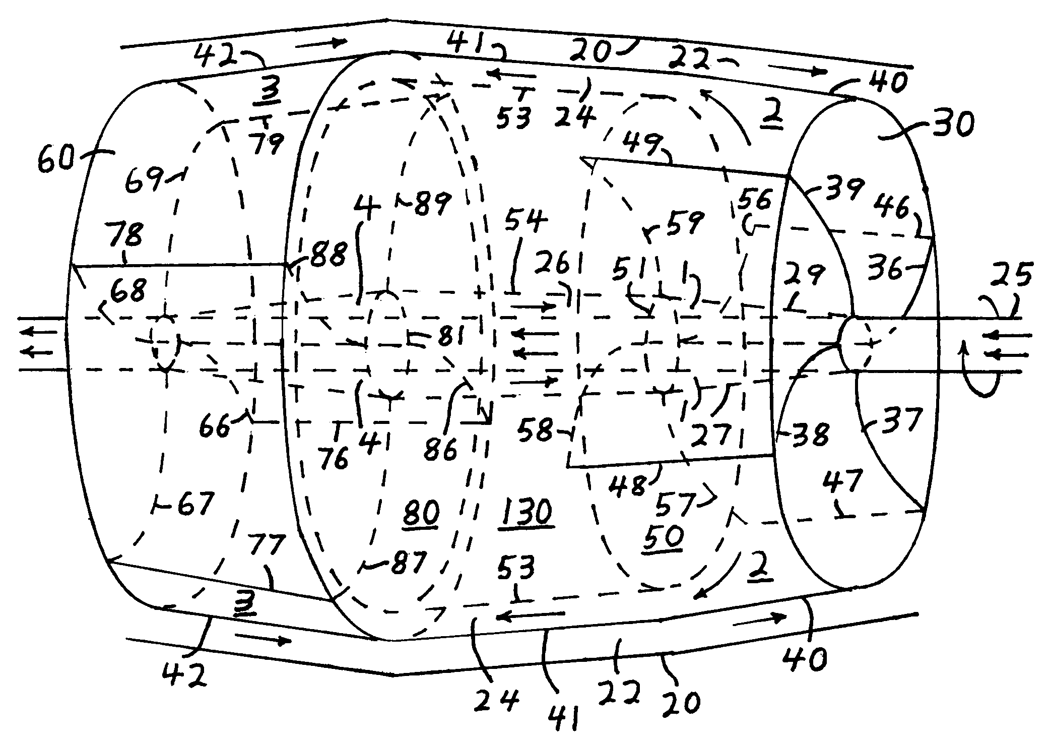
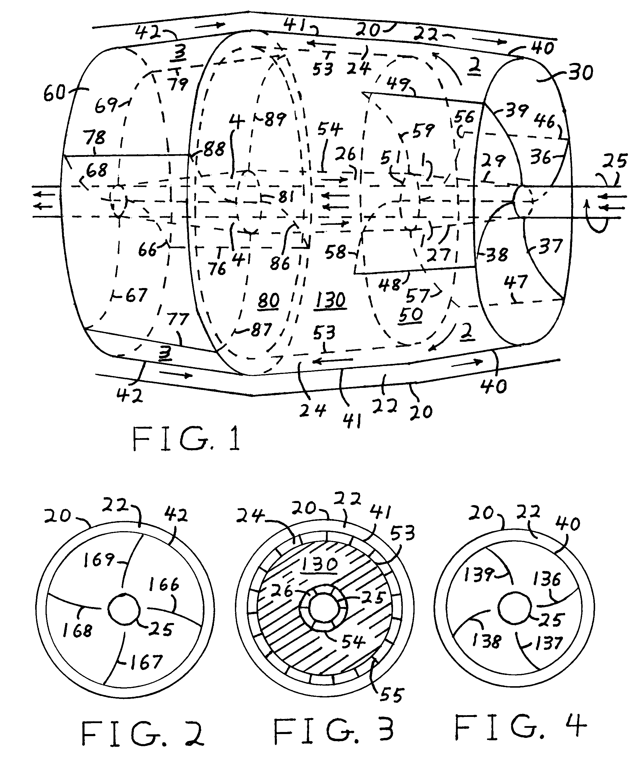
[0042]FIG. 1 shows a workable, but simplified version of the engine. Numbers 1, 2, 3, and 4 are reserved for points in the flow of the working fluid that illustrate the cycle through which the working fluid goes. Except for the containment sheet 20 on the top and bottom of the figure and used to direct a hot fluid in the channel labeled 22 between containment sheet 20 and sheet 41, all parts in the figure are rotating with a common angular velocity around the axis of the pipe 25 used to carry a cooling fluid, probably a high heat capacity liquid. The pipe 25 also carries the output torque of the engine.

[0043]The fairly thick metal sheet 30, which serves to hold in the working fluid, would best be concave when looked at from within the engine, near its center. Curved lines 36, 37, 38, and 39 represent the intersection of fan blades with sheet 30 and would best represent a firm attachment. The curved lines and thus the blades form a spiral but the spiral, for the sake of clarity in th...


PUM


Abstract

An engine / heat pump is shown. Most of its parts rotate around the same central axis. It comprises two doubly connected chambers. Blades in each chamber substantially rotate with the chamber and may be firmly attached to the walls of the chamber, thus forming a modified centrifugal pump with axial input and discharge. An expandable fluid is rotated outward by one of the pumps and then heat is added for an engine or removed for a heat pump as the fluid is being sent to the outer part of the second pump. The fluid travels toward the center of the second pump, thus impelling the pump in the rotation direction. Then heat is removed for an engine or added for a heat pump as the fluid leaves the second pump and travels back to the first pump near the center of rotation of both pumps. Rotation energy of the fluid is typically much larger than the circulation energy. A modified centrifugal pump with axial discharge having a casing rotating with the blades is also claimed.

Description

CROSS-REFERENCE TO RELATED APPLICATIONS[0001]Not Applicable—New non-provisional application none preceding on subject.FEDERALLY SPONSORED RESEARCH[0002]Not ApplicableJOINT RESEARCH PARTIES[0003]Not ApplicableREFERENCE TO A “SEQUENCE LISTING”, A TABLE, ETC.[0004]Not ApplicableBACKGROUND OF THE INVENTION[0005]1. Field of the Invention[0006]Broadly, the field is external heat engines, which can also be redesigned and used as heat pumps. Within this category the field is external heat engines or heat pumps comprising what might be described as a part of a centrifugal fan acting as a compressor and a second centrifugal fan operated backwards and acting as an expander. When I say fan I am actually talking about a compressor or an expander. The fan part differs from conventional centrifugal fans, because the output is directed with a substantial axial component as opposed to almost entirely tangential output for a standard centrifugal fan. The engine fans also differ from conventional fans...

Claims


Application Information

Patent Timeline
Patent Type & Authority Patents(United States)
IPC IPC(8): F25B27/00
CPCF01K25/00F02C1/04
Inventor GRAF, RONALD EDWARD
Owner GRAF RONALD EDWARD
Why Eureka
Try Eureka