Display device

a display device and display technology, applied in the direction of simultaneous indication of multiple variables, instruments, navigation instruments, etc., can solve the problems of lack of variety and monotony of display devices, so as to improve the visual quality of display elements, novel design, and emphasize three-dimensional appearance

Inactive Publication Date: 2011-01-25
DENSO CORP
View PDF27 Cites 13 Cited by
  • Summary
  • Abstract
  • Description
  • Claims
  • Application Information

AI Technical Summary

Benefits of technology

[0014]In the above device, the display design on the display element is not directly viewed but viewed through the light transparent element of the ornamental member. Thus, the display design appears to protrude from the surface of the display element. Further, since the light nontransparent element is adjacent to the light transparent element, the light nontransparent element emphasizes existence of the light transparent element. The visual quality of the display element is improved such that three-dimensional appearance is emphasized and novel design is provided. Thus, the device has the novel design and the high visual quality without increasing the dimensions of the device.
[0016]In the above device, since the ornamental member and the second reflection member are arranged on the display side from the surface of the display element, the visual quality of the display element is improved such that three-dimensional appearance is emphasized. Further, the reflected virtual image of the first display design is viewed on the outside of the outer periphery of the screen image. Thus, without replacing the display element to a larger one, the display region of the screen image appears to be larger. Thus, the device has the novel design and the high visual quality without increasing the dimensions of the device.

Problems solved by technology

However, in the above conventional display device, the decorative ring as a whole has translucency, accordingly, the appearance of the display device lacks variety and is monotonous.
That is, as the incident direction of the light illuminating the decorative ring is limited to a fixed direction.
Accordingly, the appearance of the decorative ring lacks variety and is monotonous.
Further, in the above conventional display device, the decorative ring as a whole has translucency, accordingly, the appearance of the display device lacks variety and is monotonous.
When a liquid crystal display device is used as a display device, to enlarge the display area, it is necessary to use a larger liquid crystal display device, which increases the costs.

Method used


Image

  • Display device
  • Display device
  • Display device

Examples


first embodiment

[0039]Hereinbelow, a display device according to the present invention will be described in an example in which the display device is applied to a combination meter 1 mounted in a vehicle, based on the drawings.

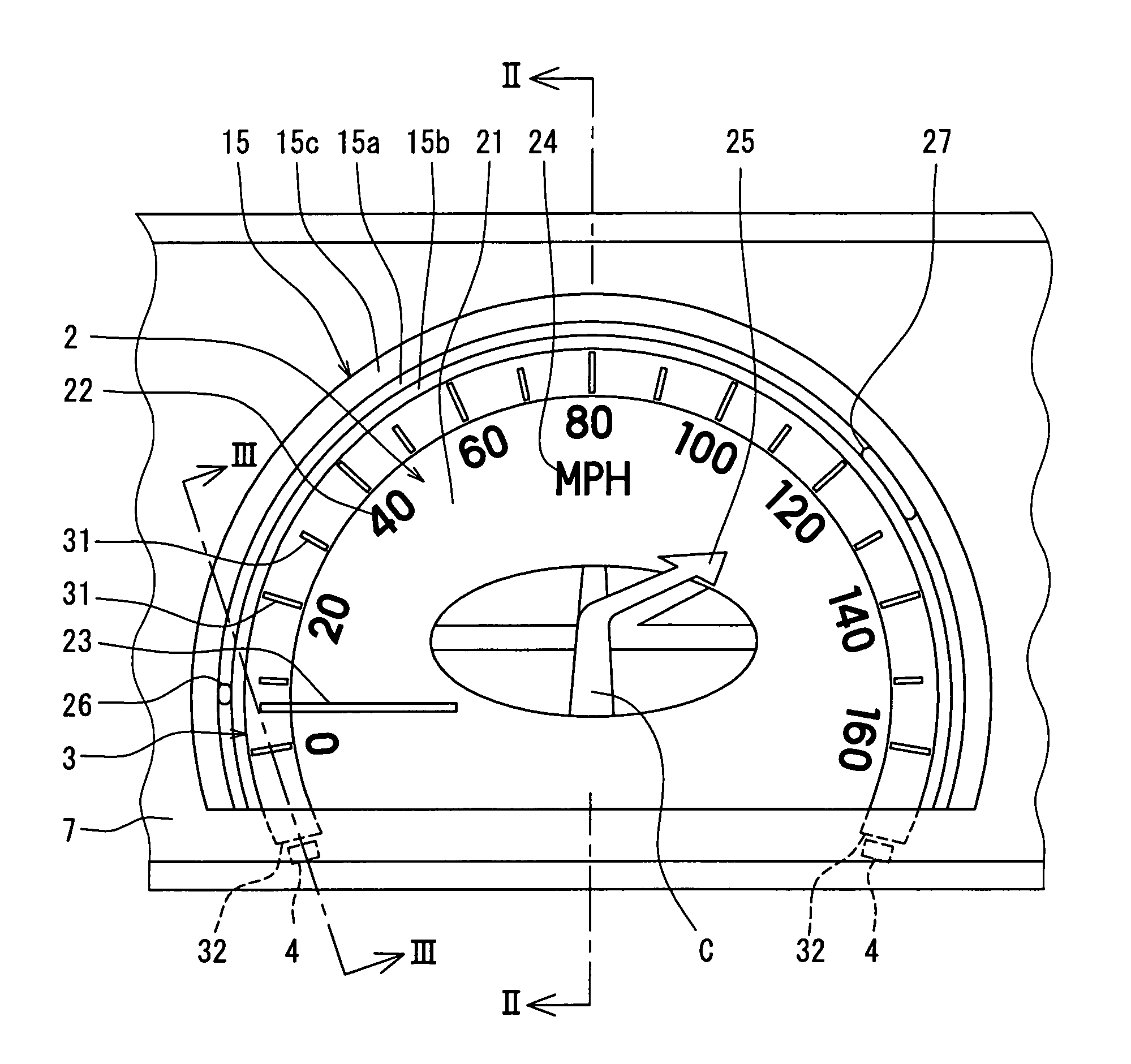
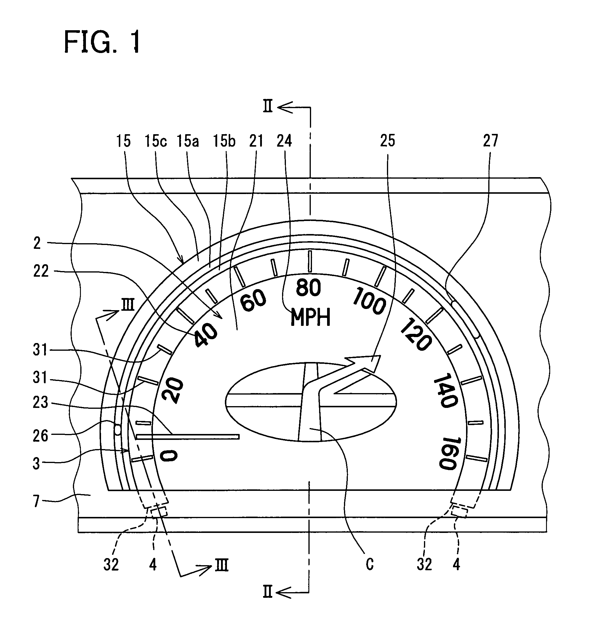
[0040]The combination meter 1 is provided in an instrument panel in a front of a driver's seat in a vehicle compartment. Information necessary for vehicle driving and information on operation statuses of the respective parts of the vehicle are displayed, as images, on an image screen 21 of a liquid crystal panel 2 as a display element, for visual recognition by the driver. In the combination meter 1, as shown in FIG. 1, a speedometer S to indicate a running speed of the vehicle and a navigation guide N to indicate a course to a destination are formed as images on the image screen 21 of the liquid crystal panel 2.

[0041]In the combination meter 1, a liquid crystal display unit is used as a display unit. More particularly, a TFT (Thin Film Transistor) type dot matrix type displa...

second embodiment

[0066]Next, the combination meter 1 according to a second embodiment of the present invention will be described.

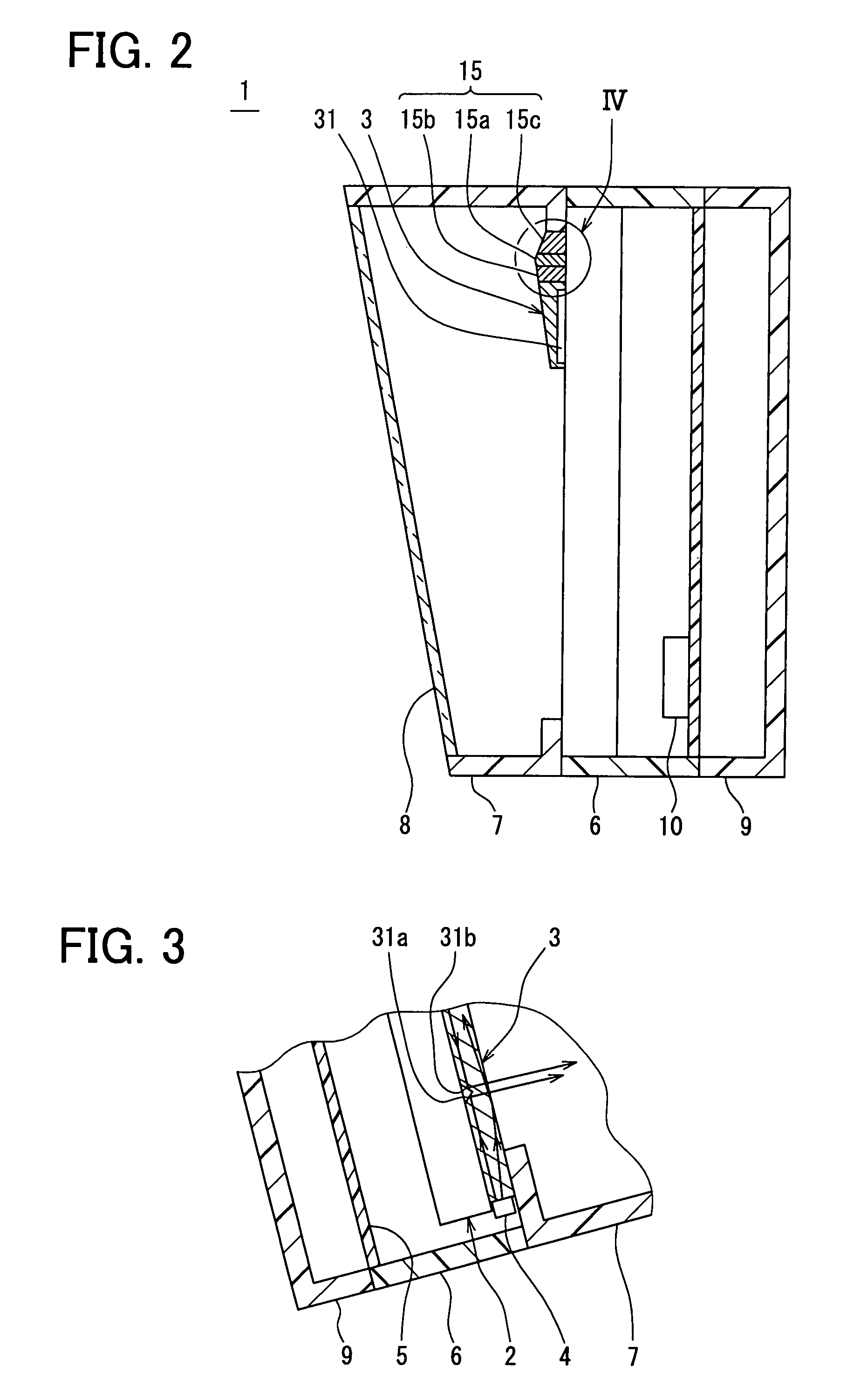
[0067]In the combination meter 1, in comparison with the combination meter 1 according to the first embodiment of the present invention, an embossed surface K as a diffuse reflection layer is formed on the surface of the front surface side of the transparent ring 15a of the decorative ring 15 as shown in FIG. 7. The embossed surface K has a large number of fine convexities and concavities formed by e.g. mold-transfer upon formation of the transparent ring 15a by mold processing of resin material. Other diffuse reflection layer than the embossed surface K may be provided as the diffuse reflection layer. For example, a bright color layer may be provided. Otherwise, a resin sheet having a diffuse reflection layer may be attached to the surface of the transparent ring 15a. As shown in FIG. 7, when the light emitted from the illumination image A proceeds in the transparent ring...

third embodiment

[0074]FIGS. 8-10 shows a combination meter according to a third embodiment of the present invention.

[0075]As shown in FIG. 8, in the image screen 21 of the liquid crystal panel 2, a pointing indicator 26 in a spot shape, as a high luminosity member with luminosity higher than that of its surrounding area, is formed as an image, in a position extended from the pointer 23 and on the scale ring 3. The pointing indicator 26 rotates about the virtual center C always integrally with the pointer 23. That is, the line-shaped pointer 23 and the high luminosity spot-shaped pointing indicator 26 in cooperation indicate the running speed. In this arrangement, novel appearance of the speedometer S can be obtained, and the visibility of the speedometer S can be improved.

[0076]Further, as shown in FIG. 8, in the image screen 21 of the liquid crystal panel 2, a course arrow indicator 27 in a line shape, as a high luminosity member with luminosity higher than that of its surrounding area, is formed ...


PUM


Abstract

A display device includes: a display element for showing information as a screen image; and an ornamental member disposed on a display surface of the display element and having a shape corresponding to the screen image. The ornamental member includes a light transparent element and a light nontransparent element. The screen image includes a designed image on a position of the display surface corresponding to the light transparent element. The display element outputs a screen image light from the display surface. The screen image light corresponding to the designed image passes through the light transparent element so that the screen image light is outputted from the ornamental member to the display side.

Description

CROSS REFERENCE TO RELATED APPLICATIONS[0001]This application is based on Japanese Patent Applications No. 2006-272239 filed on Oct. 3, 2006, No. 2006-272238 filed on Oct. 3, 2006, No. 2006-286745 filed on Oct. 20, 2006, and No. 2007-230548 filed on Sep. 5, 2007, the disclosures of which are incorporated herein by reference.FIELD OF THE INVENTION[0002]The present invention relates to a display device.BACKGROUND OF THE INVENTION[0003]As a conventional display device, a structure in which a decorative ring formed of light transmissive construction material is provided on the front surface side of a liquid crystal panel is known. The liquid crystal panel is transmission-illuminated using a backlight. The decorative ring is transmission-illuminated with light from the liquid crystal panel. The display panel is disclosed in, for example, JP-A-2006-201038 corresponding to US Patent Application Publication No. 2006 / 0158320.[0004]However, in the above conventional display device, the decora...

Claims


Application Information

Patent Timeline
Patent Type & Authority Patents(United States)
IPC IPC(8): G01D11/28
CPCB60K35/00B60K37/02G01C21/265G01C21/3626G01C21/3688G01D7/02G01D11/28G01P1/07G01P1/08G09F13/16G09F21/04G09G3/3611B60K2350/1072B60K2350/203B60K2370/155B60K2370/33B60K2370/6985G09F21/049G01D2207/30
Inventor TANE, SEIGOSUGIURA, SATOSHIKAMIYA, AKIRA
Owner DENSO CORP
Why Eureka
Try Eureka