System and method for determining a transfer function

a transfer function and system technology, applied in the field of intravascular ultrasound (ivus) arts, can solve the problems of inability to compute the transfer function in real-time, the inability to accurately represent the tissue of ultrasound data backscattered from the vascular tissue, and the inability to accurately represent the tissu

Active Publication Date: 2011-01-25
THE CLEVELAND CLINIC FOUND
View PDF43 Cites 2 Cited by
  • Summary
  • Abstract
  • Description
  • Claims
  • Application Information

AI Technical Summary

Benefits of technology

[0009]In one embodiment of the present invention, the algorithm is an iterative algorithm that is time-invariant over small intervals. In another embodiment of the present invention, the algorithm executes multiple underlying equations (e.g., an error-criteria equation, a least-squares-fit equation, etc,) and / or rely on certain selected or pre-specified parameters (e.g., a scale parameter, a shift parameter, a sign parameter, etc.). In another embodiment of the present invention, the algorithm may further be used to estimate response data for the vascular tissue. Thus, for example, execution of the algorithm may produce estimated values for both the transfer function and the response data.

Problems solved by technology

One drawback of such a system, however, is that the ultrasound data backscattered from the vascular tissue may not accurately represent the tissue.
Drawbacks of such a system, however, are that the transfer function cannot be computed in real-time (e.g., while data backscattered from vascular tissue is being acquired, etc.) and requires the use of additional components (e.g., a perfect reflector, etc.).

Method used


Image

  • System and method for determining a transfer function
  • System and method for determining a transfer function
  • System and method for determining a transfer function

Examples


Embodiment Construction

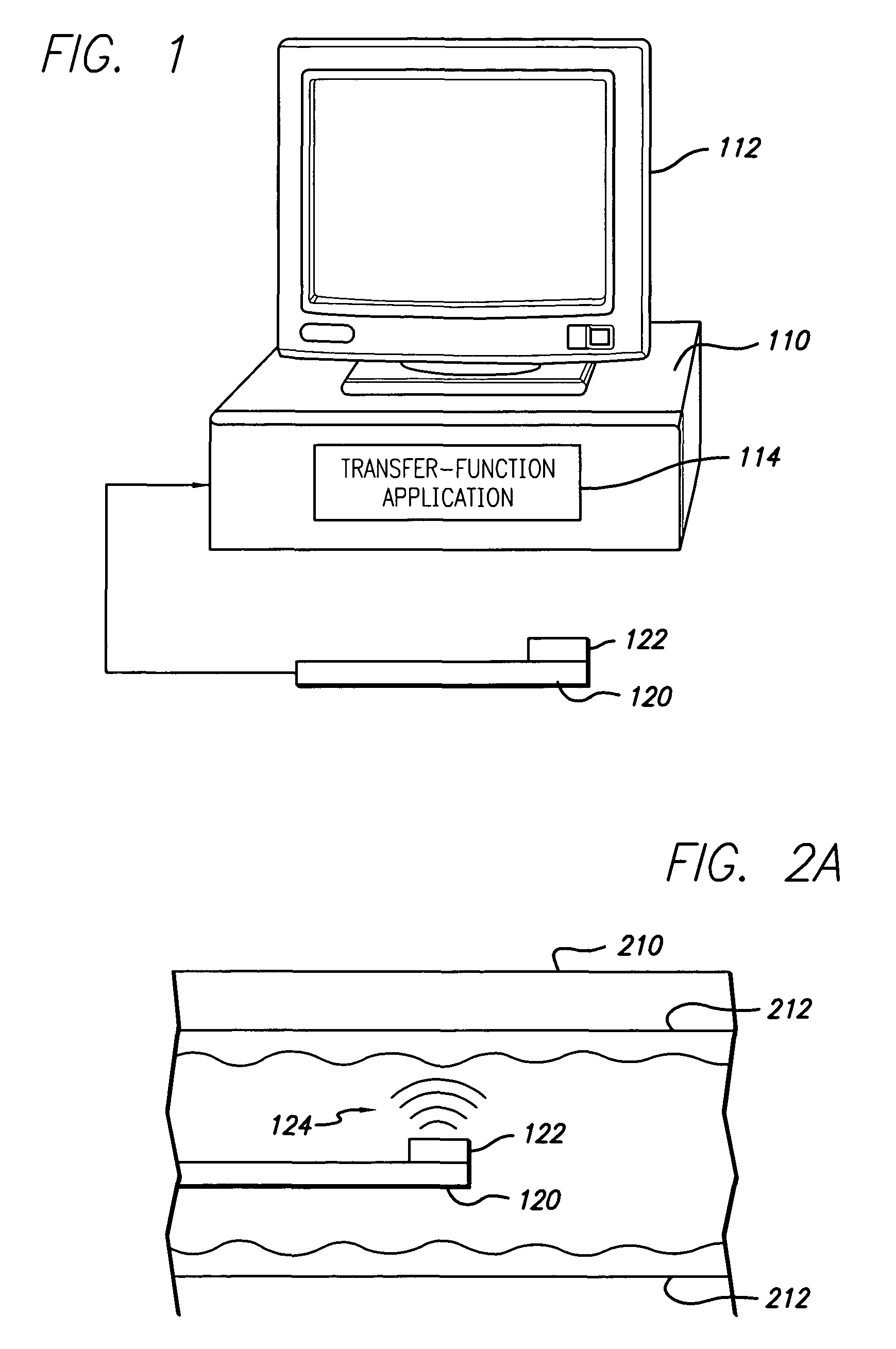
[0021]Preferred embodiments of the present invention operate in accordance with a catheter having at least one transducer, a computing device, and a transfer-function application operating thereon. In the detailed description that follows, like element numerals are used to describe like elements illustrated in one or more figures.

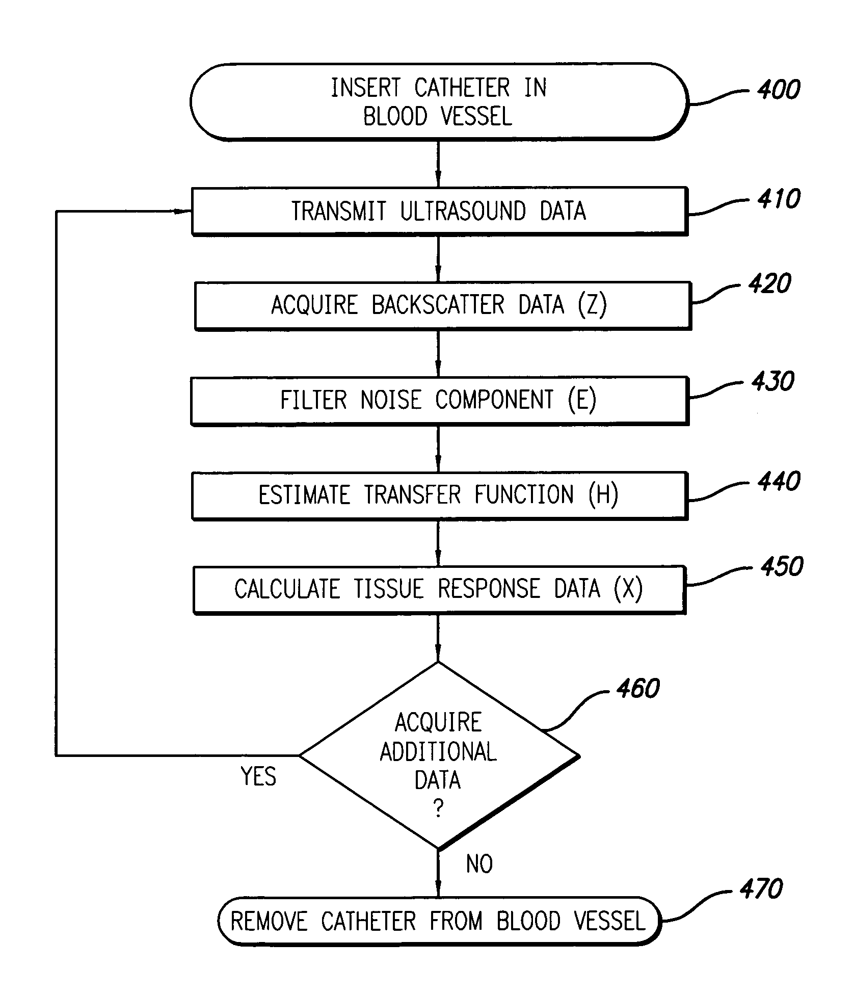
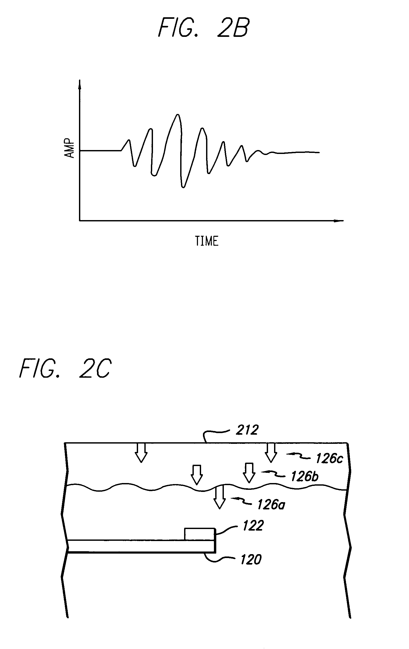
[0022]FIG. 1 illustrates an intravascular-ultrasound (IVUS) data-acquisition system operating in accordance with a first embodiment of the present invention. In this embodiment, a computing device 110 is electrically connected to a catheter 120 and used to acquire RF backscattered data from a vascular structure (e.g., a blood vessel, etc.). Specifically, as shown in FIG. 2A, the transducer 122 is attached to the end of the catheter 120 and maneuvered through a vascular structure 212 of a patient 210 to a point of interest. The transducer 122 is then pulsed (see e.g., 124) to acquire echoes or backscattered data reflected from the tissue of the vascular stru...


PUM


Abstract

A system and method is provided for using ultrasound data backscattered from vascular tissue to estimate the transfer function of a catheter (including components attached thereto—e.g., IVUS console, transducer, etc.). Specifically, in accordance with a first embodiment of the present invention, a computing device is electrically connected to a catheter and used to acquire RF backscattered data from a vascular structure (e.g., a blood vessel, etc.). The backscattered ultrasound data is then used, together with an algorithm, to estimate the transfer function. The transfer function can then be used (at least in a preferred embodiment) to calculate response data for the vascular tissue (i.e., the tissue component of the backscattered ultrasound data). In a second embodiment of the present invention, an IVUS console is electrically connected to a catheter and a computing device and is used to acquire RF backscattered data from a vascular structure. The backscattered data is then transmitted to the computing device, where it is used to estimate the catheter's transfer function and to calculate response data for the vascular tissue. The response data and histology data are then used to characterize at least a portion of the vascular tissue (e.g., identify tissue type, etc.).

Description

BACKGROUND OF THE INVENTION[0001]1. Field of the Invention[0002]The present invention relates to the intravascular-ultrasound (IVUS) arts, or more particularly, to a system and method of using ultrasound data backscattered from vascular tissue to estimate the transfer function of a catheter (including components attached thereto—e.g., IVUS console, transducer, etc.).[0003]2. Description of Related Art[0004]Ultrasound imaging of the coronary vessels of a patient can provide physicians with valuable information. For example, such an image may show the extent of a stenosis in a patient, reveal progression of disease, determine the vulnerability of the atherosclerotic plaque for causing myocardial infarction, help determine whether procedures such as angioplasty or atherectomy are indicated, or whether more invasive procedures are warranted.[0005]In a typical ultrasound imaging system, a catheter (including an ultrasonic transducer attached thereto) is carefully maneuvered through a pat...

Claims


Application Information

Patent Timeline
Patent Type & Authority Patents(United States)
IPC IPC(8): A61B8/00A61B8/12
CPCA61B5/02007A61B8/12A61B5/726
Inventor NAIR, ANUJAVINCE, D. GEOFFREYKLINGENSMITH, JON D.KUBAN, BARRY D.
Owner THE CLEVELAND CLINIC FOUND
Why Eureka
Try Eureka