
Corneal incision apparatus and blade case for storing blade unit to be mounted in the corneal incision apparatus

a corneal incision and blade unit technology, applied in the field of corn, can solve the problems of contaminated or damaged blades, troublesome mounting (attaching) or detaching the blades to or from the cutter head, and need to be sterilized or replaced, so as to facilitate the replacement of blades and prevent contamination and damage of blades

Inactive Publication Date: 2011-01-25
NIDEK CO LTD
View PDF17 Cites 0 Cited by
  • Summary
  • Abstract
  • Description
  • Claims
  • Application Information

AI Technical Summary

Benefits of technology

The present invention provides a corneal incision apparatus and a blade case that can facilitate replacement of a blade and prevent contamination and damage of the blade. The apparatus includes a blade unit with a blade for corneal incision and a cutter head unit that can hold and oscillate the blade unit. The cutter head unit has a cavity with a first opening that can hold the blade unit and a first stopper that can restrict or allow movement of the blade unit. The blade case has a cavity with a first opening that can hold the blade unit and can eject it directly. These features make the apparatus and case convenient for use and easy to replace the blade.

Problems solved by technology

Since the blade and a cutter head (a blade holder) which holds the blade are small, it is likely to take the trouble in mounting (attaching) or demounting (detaching) the blade to or from the cutter head.
If an operator or an assistant accidentally drops the blade down or strikes the blade on the cutter head during a mounting (attaching) work, the blade will be contaminated or damaged and has to be sterilized or replaced again.
Thus, there is still a risk of dropping the blade down in the process of a mounting (attaching) work (up to engagement of the blade with part of a blade oscillating mechanism in the cutter head).

Method used


Image

  • Corneal incision apparatus and blade case for storing blade unit to be mounted in the corneal incision apparatus
  • Corneal incision apparatus and blade case for storing blade unit to be mounted in the corneal incision apparatus
  • Corneal incision apparatus and blade case for storing blade unit to be mounted in the corneal incision apparatus

Examples


Embodiment Construction

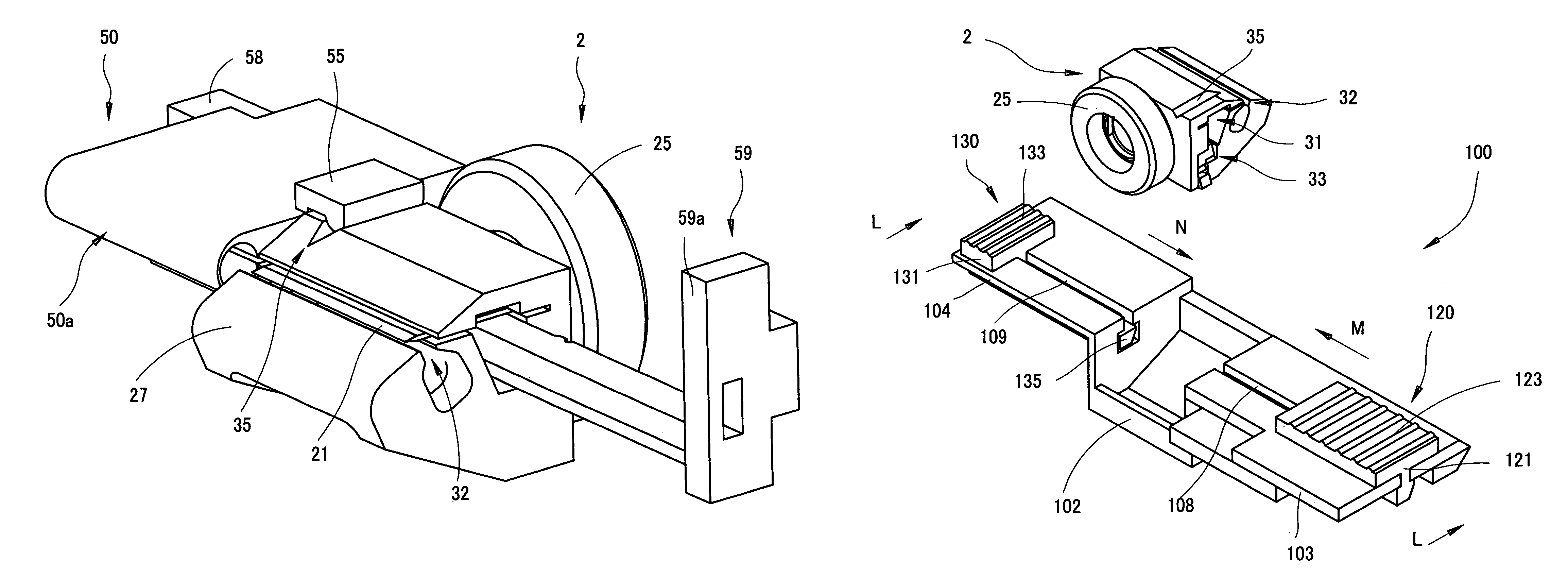
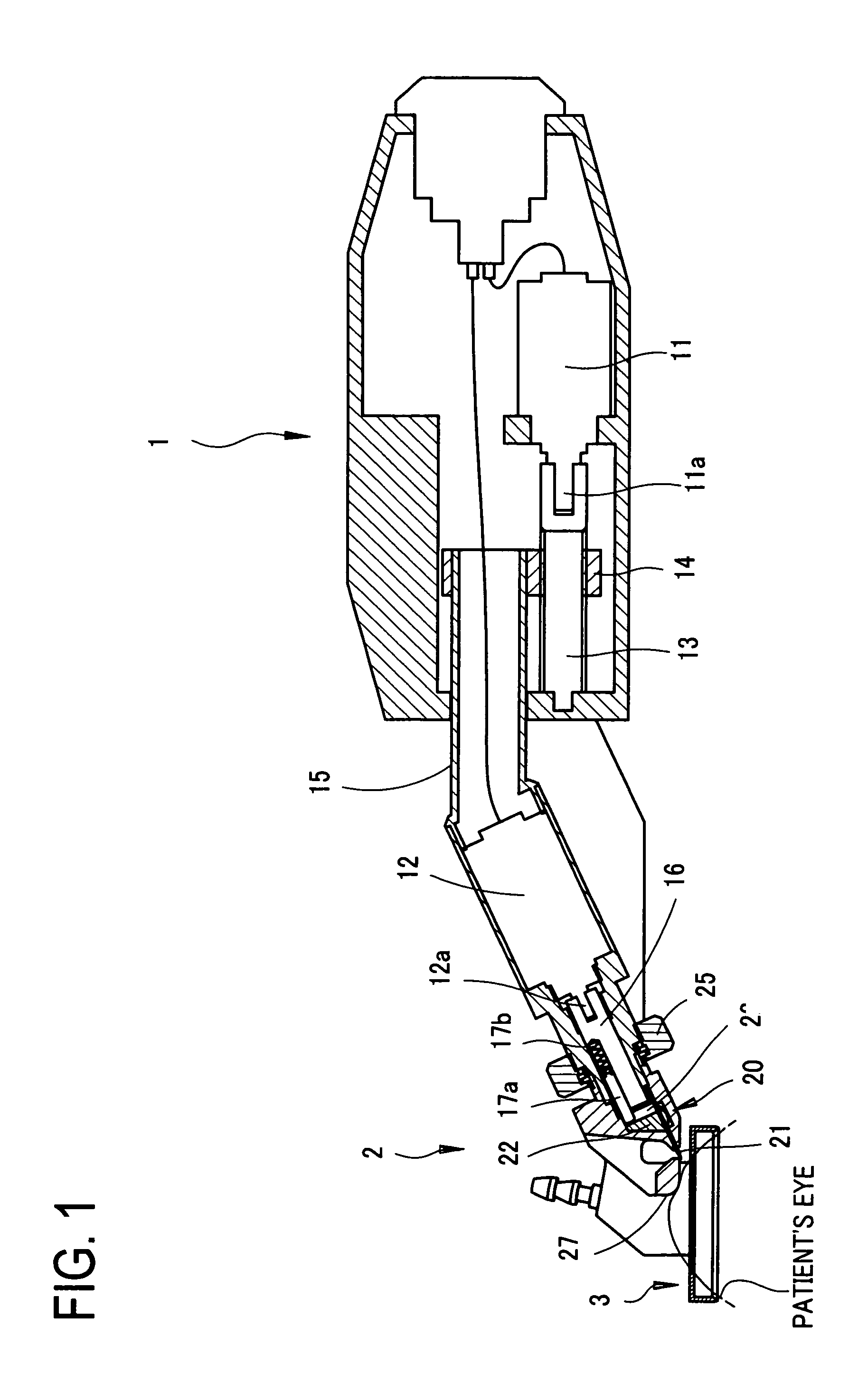
[0027]A detailed description of a preferred embodiment of the present invention will now be given referring to the accompanying drawings. FIG. 1 is a schematic configuration view of a corneal incision apparatus of the present embodiment of the present invention.

[0028]A main body 1 of the corneal incision apparatus comprises a cutter head unit 2 serving as a blade holder unit for holding a blade unit 20 for corneal incision so that the blade unit 20 is mountable / demountable (attachable / detachable) and allowed to oscillate, and a suction ring unit 3 for fixing the apparatus on a patient's eye (an operative eye). The suction ring 3 is fixed under suction to an area of the patient's eye ranging from a corneal limbus to a conjunctiva.

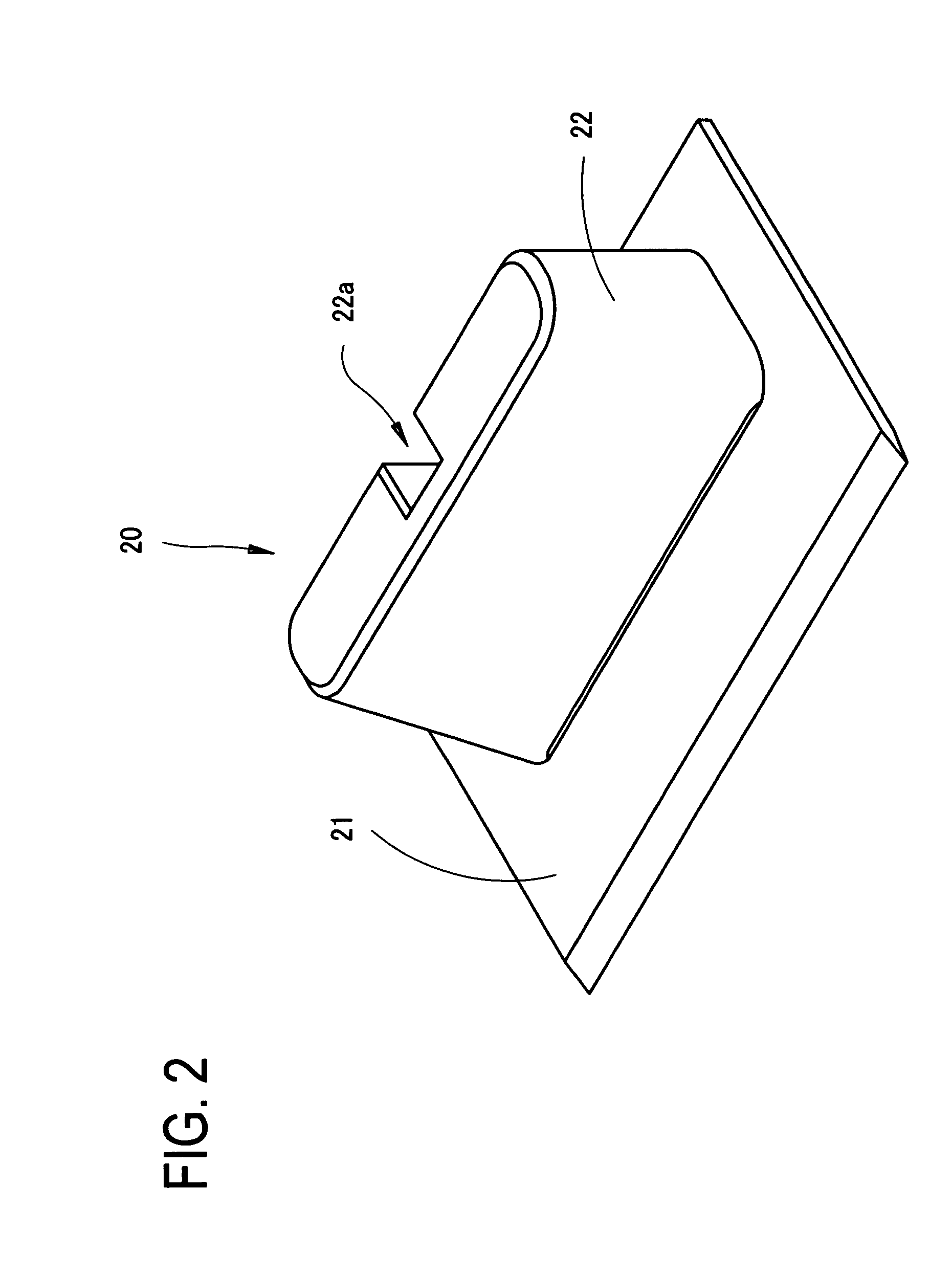
[0029]In the present embodiment, the blade unit 20 is arranged to be replaceable, and besides, the cutter head unit 2 removably attached to the main body 1 may also be arranged to be replaceable.

[0030]The blade unit 20 includes a blade 21 for corneal incisio...


PUM


Abstract

A cornea incision apparatus for incising a cornea in a layered form, comprises; a blade unit having a blade for corneal incision; and a cutter head unit arranged to detachably hold the blade unit in such a manner as to allow oscillation thereof, the cutter head unit including; a cavity formed with a first opening which opens to the outside to allow direct mounting / demounting of the blade unit, and arranged to hold the blade unit in such a manner as to allow oscillation thereof; and a first stopper provided in the first opening, the first stopper being movable between a first position for restricting movement of the blade unit in the first opening and a second position for allowing the movement of the blade unit in the first opening.

Description

BACKGROUND OF THE INVENTION[0001]1. Field of the Invention[0002]The present invention relates to a corneal incision apparatus for incising a cornea in a layered form, and a blade case for storing a blade unit which is mounted (loaded) in and used with the corneal incision apparatus.[0003]2. Description of Related Art[0004]As known operative procedures of corneal surgery for ablating part of a cornea by an excimer laser beam or the like, there are a LASIK (laser assisted in-situ keratomileusis) surgery wherein a flap is formed by incising a portion with a thickness of about 150 μm ranging from an epithelium to a midportion of a corneal stroma in a layered form, and an Epi-LASIK (Epithelial LASIK) surgery wherein a flap is formed by incising only an epithelium in a layered form, and others. As a device for incising a cornea in a layered form, a corneal incision apparatus called “keratome” has been used.[0005]The corneal incision apparatus is arranged to incise a cornea in a layered fo...

Claims


Application Information

Patent Timeline
Patent Type & Authority Patents(United States)
IPC IPC(8): A61F9/00
CPCA61F9/0133
Inventor SUGIMURA, MASAHIRO
Owner NIDEK CO LTD
Learn More