Antenna near-field probe station scanner

a scanner and probe station technology, applied in the field of scanners, can solve the problems of adversely affecting the characterization, time-consuming and expensive procedures, and conventionally tested results not always producing the true radiation pattern of the antenna

Inactive Publication Date: 2011-01-25
ADMINISTATOR OF NAT AERONAUTICS & SPACE ADMINISTATION U S GOVERNMENT AS REPRESENTED BY THE +1
View PDF24 Cites 53 Cited by
  • Summary
  • Abstract
  • Description
  • Claims
  • Application Information

AI Technical Summary

Problems solved by technology

Conventionally the antennas must be separated using a procedure that is very time consuming and expensive.
The antenna must he isolated from the fixture, or the fixture will adversely effect the characterization.
Accordingly, the conventionally tested results do not always produce the true radiation pattern of the antenna.

Method used


Image

  • Antenna near-field probe station scanner
  • Antenna near-field probe station scanner
  • Antenna near-field probe station scanner

Examples


Embodiment Construction

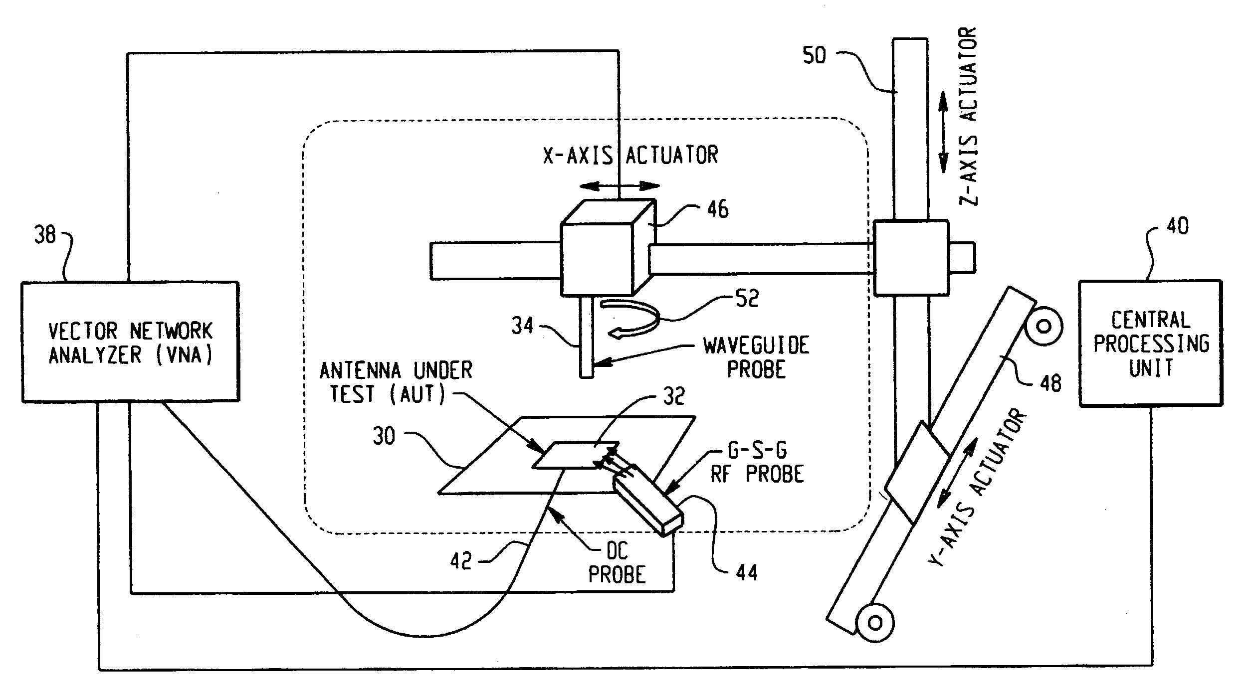
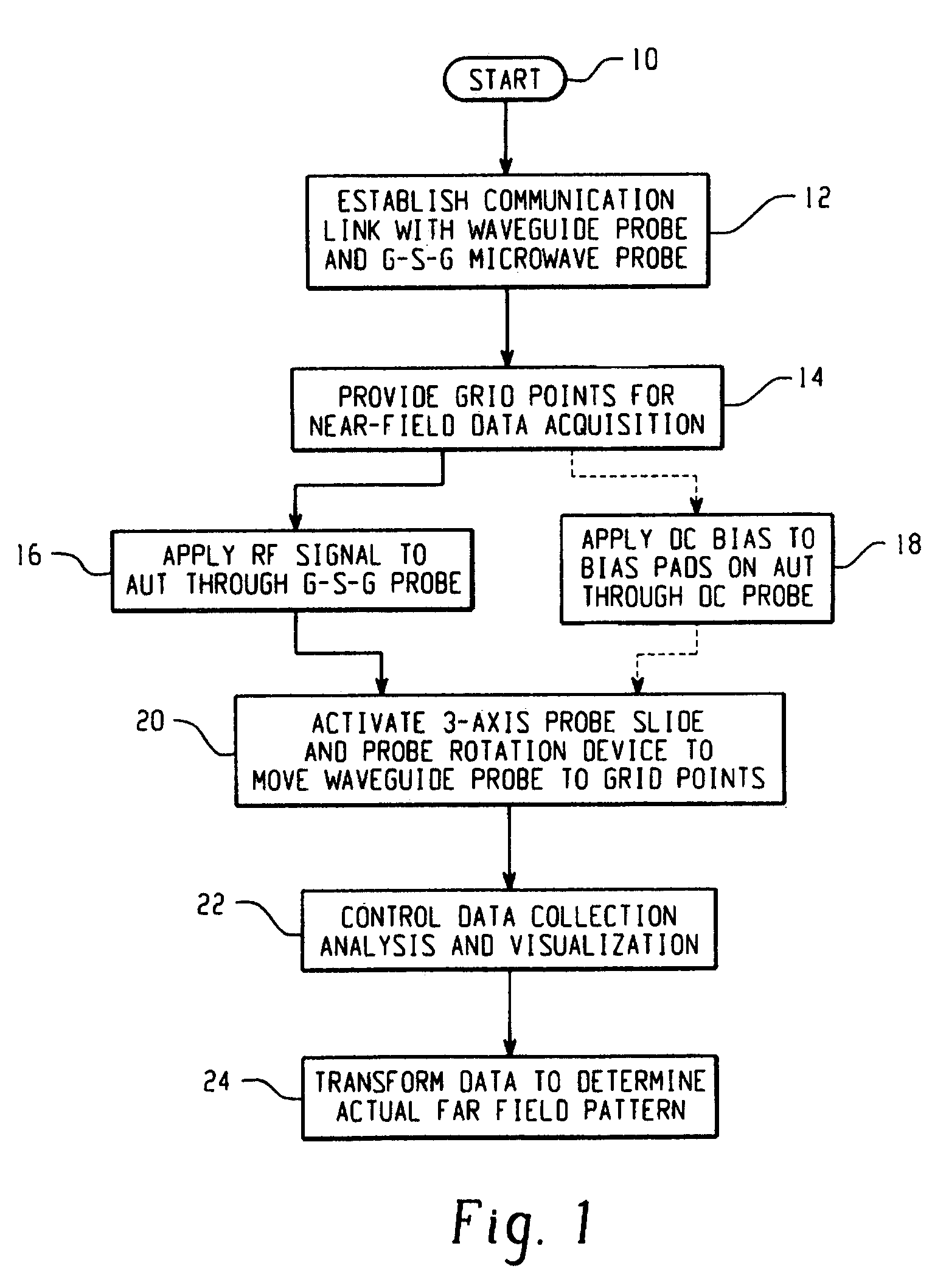
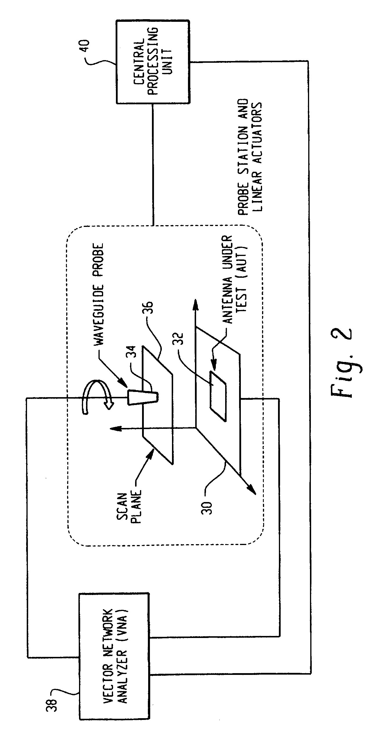
[0030]The present invention relates to antenna metrology hardware for non-destructive characterization of miniaturized passive or active antennas fabricated on substrates (e.g., Gallium Arsenide (GaAs), Silicon (Si), Lanthanum Aluminate (LaAlO3, etc.) which are difficult to measure in traditional ranges because of their smaller size, fragility, and non-trivial DC biasing or complicated fixturing requirements. For the purposes of the present invention, miniaturized antennas are those having a dimension of about 1 cm or less, down to 1 mm or even smaller. Stated differently, these small antennas have a cross sectional size of about ⅕ to about ½ lambda, whereas large antennas have a size greater than ½ lambda. The scanner consists of a precision mechanical slide system, software analysis features, a probe station, and an automatic network analyzer. The turn-key antenna near-field data acquisition system in this scanner is extremely fast, automated, and user friendly. It only requires u...


PUM


Abstract

A miniaturized antenna system is characterized non-destructively through the use of a scanner that measures its near-field radiated power performance. When taking measurements, the scanner can be moved linearly along the x, y and z axis, as well as rotationally relative to the antenna. The data obtained from the characterization are processed to determine the far-field properties of the system and to optimize the system. Each antenna is excited using a probe station system while a scanning probe scans the space above the antenna to measure the near field signals. Upon completion of the scan, the near-field patterns are transformed into far-field patterns. Along with taking data, this system also allows for extensive graphing and analysis of both the near-field and far-field data. The details of the probe station as well as the procedures for setting up a test, conducting a test, and analyzing the resulting data are also described.

Description

[0001]The invention described herein was made by civil servant employees of the United States Government, and a non-civil servant employee working under a NASA contract, and is subject to the provisions of Section 305 of the National Aeronautics and Space Act of 1958, Public Law 85-568 (72 Stat. 435; 42 U.S.C. 2457).FIELD OF THE INVENTION[0002]The present invention relates generally to a scanner device for the measurement of miniaturized antennas using near- field signals. More particularly, it relates to a probe station scanner for measuring near-field radiated power performance of a miniaturized antenna, and for transforming the measurements into far-field characteristics.RELATED ART[0003]Before an antenna can be used for a particular application, the antenna must first be tested to determine its performance characteristics. One characteristic, the radiation pattern, is generally tested in an antenna range. Antenna range types are numerous, and the choice of range to use is depend...

Claims


Application Information

Patent Timeline
Patent Type & Authority Patents(United States)
IPC IPC(8): G01R29/10
CPCG01R29/105H01Q3/08
Inventor ZAMAN, AFROZ J.LEE, RICHARD Q.DARBY, WILLIAM G.BARR, PHILIP J.LAMBERT, KEVIN MMIRANDA, FELIX A.
Owner ADMINISTATOR OF NAT AERONAUTICS & SPACE ADMINISTATION U S GOVERNMENT AS REPRESENTED BY THE
Why Eureka
Try Eureka