Unlock instant, AI-driven research and patent intelligence for your innovation.

Optical disk drive control circuit

a control circuit and optical disk technology, applied in the direction of digital signal error detection/correction, instruments, recording signal processing, etc., can solve the problems of information not being able to obtain information based on the reflection of light from the disk, information cannot be read out correctly from the optical disk,

Inactive Publication Date: 2011-01-25
RENESAS ELECTRONICS CORP
View PDF7 Cites 2 Cited by
  • Summary
  • Abstract
  • Description
  • Claims
  • Application Information

AI Technical Summary

Benefits of technology

The present invention provides a solution for an optical disk device by controlling the objective lens when a light beam passes through a flaw or defect in the disk. The invention involves applying alternating accelerations to the objective lens in plus and minus directions to cancel out displacement caused by the accelerations. This allows the objective lens to quickly return to its normal position or a position in the vicinity thereof, even after the flaw or defect has passed. The invention provides a circuit and a method for controlling the objective lens to ensure that it remains in the focused or tracking position during operation.

Problems solved by technology

As mentioned above, the control of the related art has eventually a problem that information cannot read out correctly from the optical disk in the ‘b’, ‘c’ and subsequent durations corresponding to the size (that is, an error range where reading of correct information becomes an error) of the defect, in particular, in the duration ‘d’.
There may occur such a situation that information based on the reflection of light from the disk 1 cannot be obtained due to a flaw, a defect or the like on the disk 1.

Method used


Image

  • Optical disk drive control circuit
  • Optical disk drive control circuit
  • Optical disk drive control circuit

Examples


embodiment 1

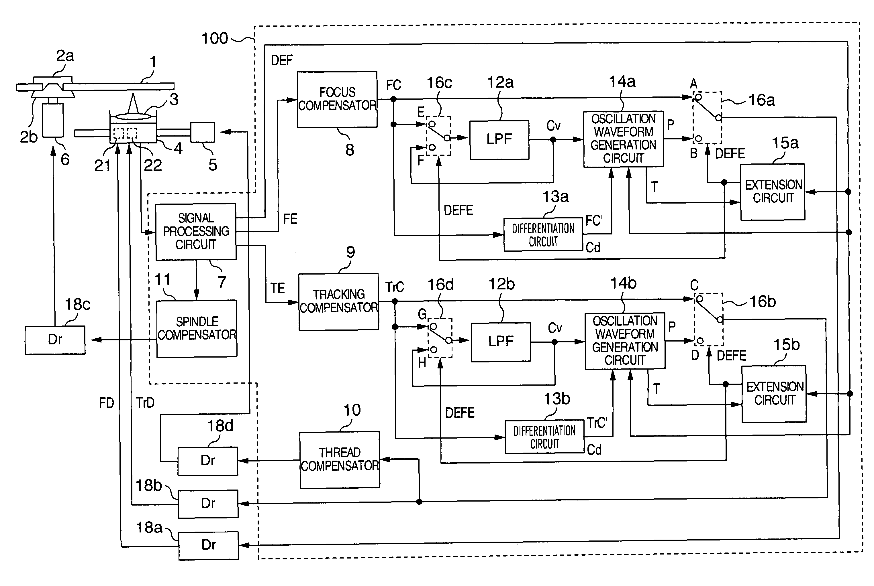
[0027]FIG. 1 is an arrangement of an optical disk device in accordance with an embodiment 1 of the present invention, showing, in particular, details of a circuit (drive control circuit) associated with servo control. The optical disk device has, as hardware and driver (drive circuit) part for driving a disk 1, a clamper 2a, a turntable 2b, an objective lens 3, a pickup (optical pickup) 4, a thread motor 5, and a spindle motor 6, which are driven by drive circuits (Drs) 18a, 18b, 18c, and 18d respectively. The optical disk device also has an IC (semiconductor integrated circuit device) 100 having a circuit for performing drive control or mainly servo control mounted therein. The pickup 4 is connected with the objective lens 3 and is provided with actuators 21, 22 for actuating the objective lens 3.

[0028]The IC 100 has a signal processing circuit 7, a focus compensator 8, a tracking compensator 9, a thread compensator 10, a spindle compensator 11, low-pass filters (LPFs) 12a, 12b, di...

embodiment 2

[0066]Explanation will next be made as to an optical disk device in accordance with an embodiment 2, by referring to FIGS. 6 to 8. The embodiment 2 is different from the embodiment 1 in the driving control of returning the objective lens to the normal position and in waveforms.

[0067]FIG. 6 shows details of a circuit (drive control circuit) part of an arrangement of the optical disk device of the embodiment 2 of the present invention, in particular, associated with servo control. The arrangement of FIG. 6 is different from that of FIG. 1 not in the oscillation waveform generation circuits 19a, 19b but in provision of acceleration generation circuits 19a, 19b. Explanation will be made as to only a part of the embodiment 2 different from the embodiment 1.

[0068]A means for generating a signal to apply acceleration to the objective lens 3 is implemented in the form of a feedforward control system mainly including the acceleration generation circuits 19a, 19b.

[0069]The focus control will...


PUM

PropertyMeasurementUnit
frequencyaaaaaaaaaa
accelerationaaaaaaaaaa
polaritiesaaaaaaaaaa

Abstract

An IC provided in an optical disk device having an objective lens and a pickup for a disk. The IC has a circuit for holding a signal which drives the objective lens in a focus or tracking direction and for detecting the moving direction of the objective lens, and a circuit for generating a signal which applies an acceleration to the objective lens. When the objective lens passes through a defect on the disk, on the basis of the detected moving direction of the objective lens, the IC applies the acceleration alternately in plus and minus directions to the objective lens to make the objective lens stationary. As a result, after the defect passage, the objective lens can be quickly returned to a focused point or an on-track position and reproducing / recording operation can be resumed.

Description

INCORPORATION BY REFERENCE[0001]The present application claims priorities from Japanese applications JP2005-369519 filed on Dec. 22, 2005, JP2006-290154 filed on Oct. 25, 2006, the contents of which are hereby incorporated by reference into this application.BACKGROUND OF THE INVENTION[0002]The present invention relates to an optical disk device, a circuit, or an IC (semiconductor integrated circuit device) provided for the optical disk medium, for optically reproducing (reading) or recording a signal (data / information) from / to an optical disk medium.[0003]In a related art optical-disk device technique, a flaw or a defect (which will be abbreviated merely to defect, hereinafter) is coped with by controlling the optical disk device in such a manner that the device is put in a state immediately before passage of the defect on the disk after the defect passage under servo control.[0004]There is such a description in Jp-A-2000-90467 that, when a large fluctuation component is included in...

Claims


Application Information

Patent Timeline
Patent Type & Authority Patents(United States)
IPC IPC(8): G11B7/00
CPCG11B7/0948
Inventor TADA, YUKINOBU
Owner RENESAS ELECTRONICS CORP