
Optical rotating data transmission device of short overall length

a transmission device and optical rotating technology, applied in the direction of transmission, electromagnetic transmission, instruments, etc., can solve the problem of long overall length, and achieve the effect of reducing the overall length of the arrangemen

Active Publication Date: 2011-01-25
SCHLEIFRING & APPBAU
View PDF78 Cites 8 Cited by
  • Summary
  • Abstract
  • Description
  • Claims
  • Application Information

AI Technical Summary

Benefits of technology

[0008]The invention is based on the object of improving the known state of the art of rotating data transmission devices for transmitting optical signals, and to develop it specifically so that the overall length of the arrangement is reduced.

Problems solved by technology

The disadvantage of this system is also the long overall length.

Method used


Image

  • Optical rotating data transmission device of short overall length
  • Optical rotating data transmission device of short overall length
  • Optical rotating data transmission device of short overall length

Examples


Embodiment Construction

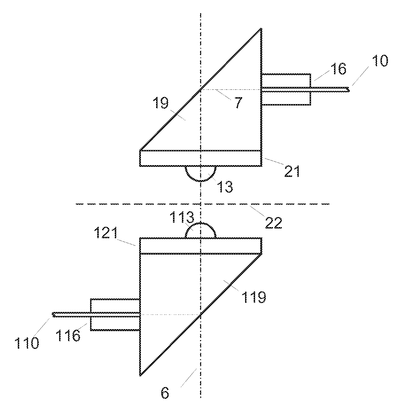
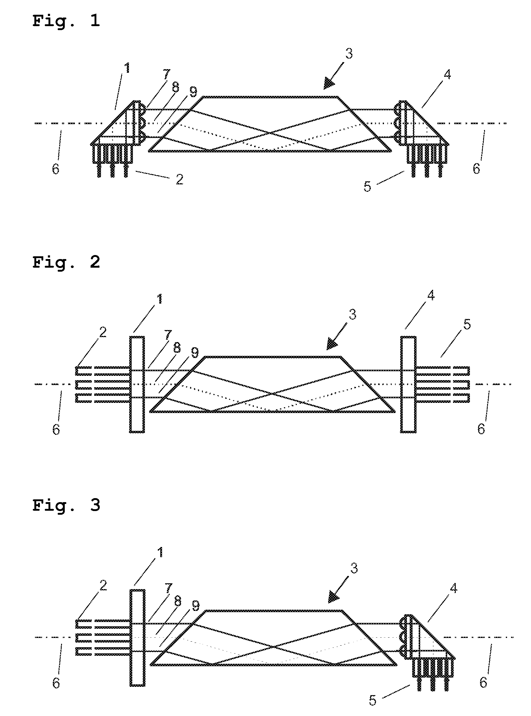
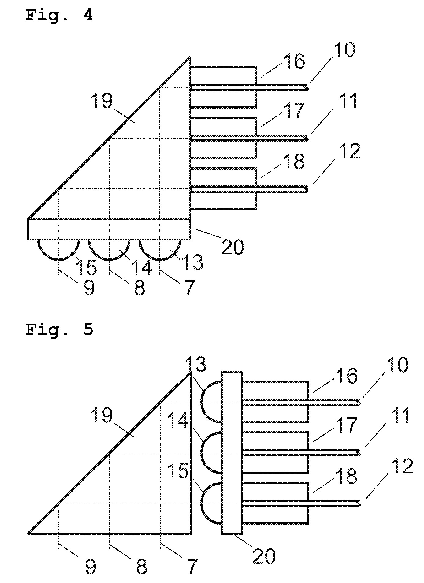
[0025]FIG. 1 shows in schematic form a cross-section through an arrangement in accordance with the invention along a rotation axis 6. The optical rotating data transmission device in accordance with the invention comprises a first collimator arrangement 1 for coupling-on a first set of optical waveguides 2, and also a second collimator arrangement 4 for coupling-on a second set of optical waveguides 5. A derotating optical element 3, which in this case is a Dove prism, is disposed between the first collimator arrangement 1 and the second collimator arrangement 4. A beam path of three light rays 7, 8, 9 illustrates the way the arrangement works. Light can therefore be coupled-in, for example, through one of the first optical waveguides 2 perpendicularly to the rotation axis. The light is deflected and collimated in the first collimator arrangement 1 in a direction parallel to the rotation axis, derotated with the Dove prism 3, and coupled into the second collimator arrangement 4. The...


PUM


Abstract

An optical rotating data transmission device comprises a first collimator arrangement for coupling-on first optical waveguides, a second collimator arrangement for coupling-on second optical waveguides, which is supported to be rotatable relative to the first collimator arrangement about a rotation axis, and a derotating element such as a Dove prism in a light path between the collimator arrangements. At least one collimator arrangement comprises a deflecting element which deflects light entering the device from optical waveguides positioned at an angle to the direction of the rotation axis to travel along the direction of the rotation axis, or deflects light traveling along the direction of the rotation axis to exit the device at an angle to the rotation axis towards optical waveguides.

Description

CROSS REFERENCE TO RELATED APPLICATIONS[0001]The present application claims priority to pending German Patent Application No. 102007029503.2 filed Jun. 25, 2007, and incorporated herein by reference.BACKGROUND OF THE INVENTION[0002]1. Field of the Invention[0003]The invention relates to a device for transmitting optical signals between units that are rotatable relative to each other, which device is also known as a rotary coupling or a rotary joint. With this, preferably a plurality of optical signals can be transmitted simultaneously in a plurality of channels.[0004]2. Description of the Related Art[0005]Various transmission systems are known for transmitting optical signals between units that are rotatable relative to each other.[0006]U.S. Pat. No. 5,568,578 discloses an optical rotating data transmission device for a plurality of channels, with a Dove prism. For coupling light into or out of glass fibers, an arrangement with a plurality of GRIN lenses is provided. The GRIN lenses...

Claims


Application Information

Patent Timeline
Patent Type & Authority Patents(United States)
IPC IPC(8): G02B6/26H04B10/00
CPCG02B6/3604G02B27/642H04B10/22G02B3/0006G02B3/0087H04B10/801
Inventor POPP, GREGORWINKLER, MAX
Owner SCHLEIFRING & APPBAU
Learn More