Method and system for identifying a malfunctioning compressed air consumer circuit in a vehicle electronic compressed air system

a consumer circuit and compressed air technology, applied in the direction of positive displacement liquid engines, process and machine control, instruments, etc., can solve problems such as circuit shutoff and circuit shutoff prematurely

Active Publication Date: 2011-01-25
WABCO EURO BVBA SPRL
View PDF35 Cites 1 Cited by
  • Summary
  • Abstract
  • Description
  • Claims
  • Application Information

AI Technical Summary

Benefits of technology

[0004]The present invention includes measuring a variable of state (pressure, air flow rate, air mass, energy) of the individual compressed air consumer circuits and determining whether the measured variable of state or possibly the negative gradient of the variable of state determined for a predefined time satisfies a circuit-failure criterion. The compressed air consumer circuit in question is shut off only when this circuit-failure criterion is satisfied. By virtue of this inventive measure, premature shutoff of compressed air consumer circuits in response to brief dynamic pressure collapses is prevented, for example during intensive braking events. As a result, enhanced vehicle safety is achieved by improved energy supply to compressed air consumer circuits that already have a low pressure level due to air consumption. The present invention ensures that compressed air consumer circuits that already have a low pressure level will be supplied with compressed air for a longer time.

Problems solved by technology

A disadvantage of the known multi-circuit protective valves is that they react to such dynamic pressure collapses and shut off the circuit in question if such circuit has a low pressure level.
The occurrence of such momentary dynamic pressure collapses, therefore, leads, at low pressure level, to premature shutoff of circuits, even though the respective pressure at the end of the event (i.e., at the end of the pressure collapse) would still be higher than the closing pressure.

Method used


Image

  • Method and system for identifying a malfunctioning compressed air consumer circuit in a vehicle electronic compressed air system
  • Method and system for identifying a malfunctioning compressed air consumer circuit in a vehicle electronic compressed air system
  • Method and system for identifying a malfunctioning compressed air consumer circuit in a vehicle electronic compressed air system

Examples


Embodiment Construction

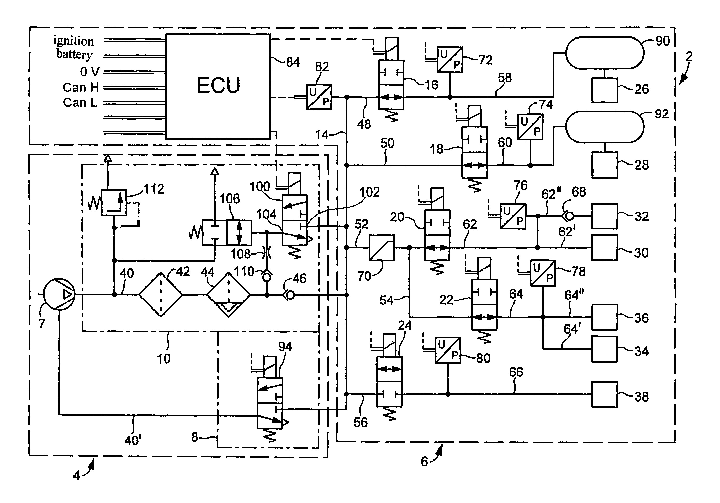
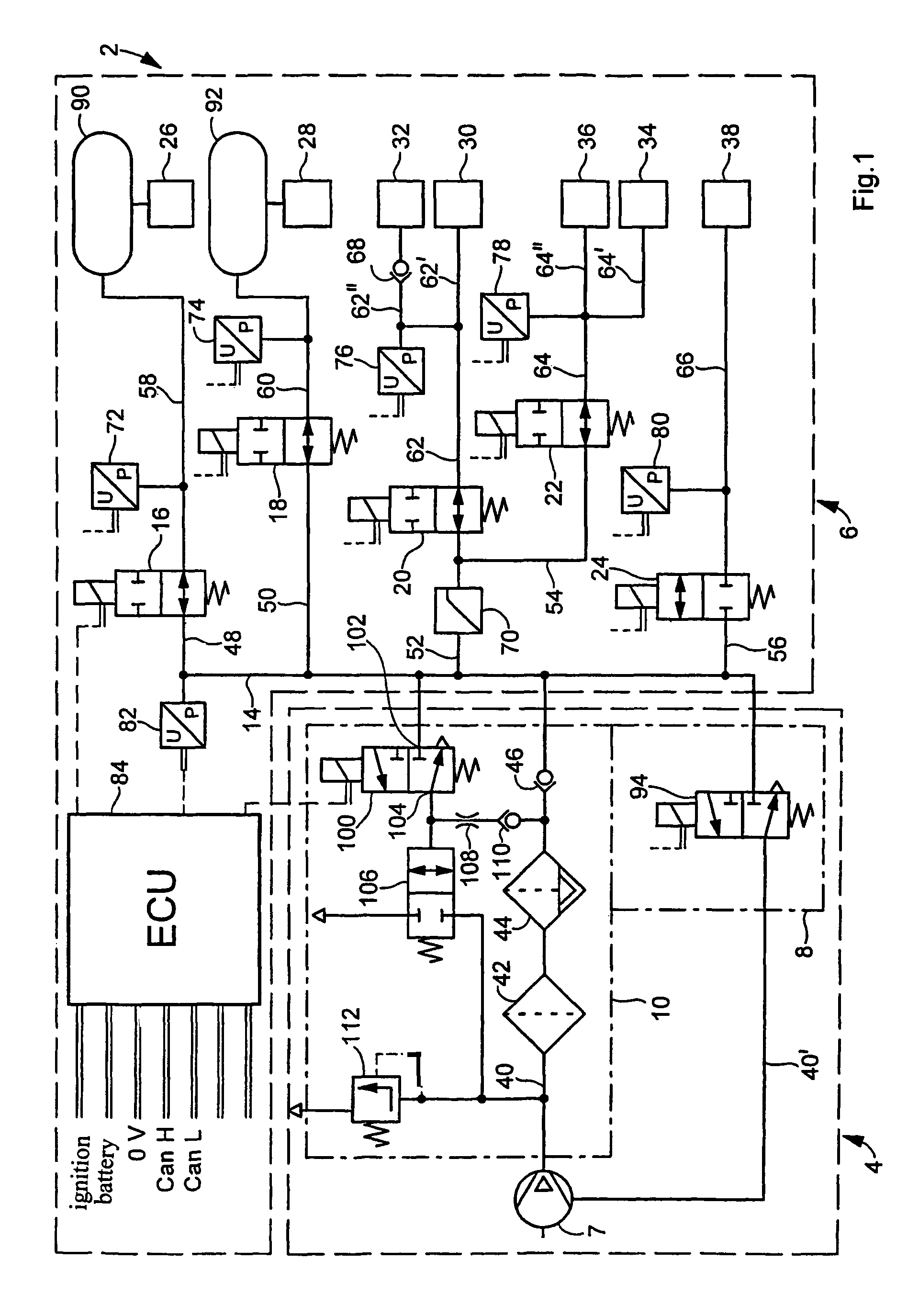
[0010]Referring now to FIG. 1, where pressurized-fluid lines are represented by solid lines and electrical lines by broken lines, there is shown a compressed air system 2 with a compressed air supply part 4 and a consumer part 6. Compressed air supply part 4 includes a compressor 7, a compressor control device 8 and an air-dryer part 10.

[0011]Consumer part 6 is provided with a compressed air distributor line 14, a plurality of electrically actuatable valves, preferably solenoid valves 16, 18, 20, 22, 24 with restoring springs and a plurality of compressed air consumer circuits 26, 28, 30, 32, 34, 36, 38 supplied with compressed air via the solenoid valves.

[0012]From compressor 7, a compressed air supply line 40 leads via a filter 42, an air dryer 44 and a check valve 46 to distributor line 14, from which there are branched off lines 48, 50, 52, 54, 56 leading to the solenoid valves. From the solenoid valves, compressed air lines 58, 60, 62, 64, 66 lead to the consumer circuits. Line...


PUM


Abstract

To detect a failure of a compressed air consumer circuit in a compressed air system for vehicles, pressure is continuously measured in compressed air consumer circuits and evaluated in an electronic control unit which compares the pressure values and / or determined negative pressure gradients of the compressed air consumer circuits with a respective threshold value and shuts off an air-consumer circuit if the pressure values and / or negative pressure gradients thereof satisfy a circuit-failure criterion. The circuit-failure criterion is satisfied when the pressure values and / or pressure gradients are below the respective threshold value for a time equal to or longer than the time of a dynamic pressure change or of a dynamic pressure collapse.

Description

BACKGROUND OF THE INVENTION[0001]The present invention relates to an improved method and system for detecting a failure of a compressed air consumer circuit in an electronic compressed air system for vehicles.[0002]Multi-circuit protective valves are known that divide an energy supply into several mutually independent consumer circuits and, in the event of failure of one consumer circuit, for example by line rupture, maintain a minimum pressure in the intact circuits. If a defect allowing more air to be lost than can be resupplied by the compressor occurs in a service-brake circuit, the pressure in the service-brake circuit drops mutually until the pressure reaches the closing pressure of the valve. The pressure in the defective circuit continues to drop, whereas the closing pressure is maintained in the intact circuits. While the pressure in the defective circuit continues to drop, the circuits that are still intact can be refilled by the compressor until the opening pressure of th...

Claims


Application Information

Patent Timeline
Patent Type & Authority Patents(United States)
IPC IPC(8): G06F7/00F02B23/00F04B49/00B60T13/68B60T17/02B60T17/18B60T17/22
CPCB60T13/68B60T17/02B60T17/18B60T17/22
Inventor DETLEFS, CARSTENDIEKMEYER, HEINRICHLIPPELT, FRANK-DIETMARREINHARDT, JOACHIMSTRILKA, BERND
Owner WABCO EURO BVBA SPRL
Why Eureka
Try Eureka