
Biomass harvesting system

a biomass harvesting and biomass technology, applied in baling, picking devices, agricultural tools and machines, etc., can solve the problems of increasing costs and the use of the term ‘biomass’, and achieve the effect of efficient harvesting of biomass of agricultural plant growth

Inactive Publication Date: 2011-02-01
CROSBY LON OWEN
View PDF11 Cites 49 Cited by
  • Summary
  • Abstract
  • Description
  • Claims
  • Application Information

AI Technical Summary

Benefits of technology

[0011]The present invention is directed to a biomass harvesting system that satisfies the need for a system to efficiently harvest biomass of agricultural plant growth from an agricultural field while intelligently analyzing the topsoil characteristics to assist in determining the quantity of agricultural plant growth to harvest. The biomass harvesting system comprises in operative combination a power source for providing mechanical and electric power to the system, a biomass accumulator for producing discrete units ...

Problems solved by technology

The resulting rise in energy demands have coupled with rising costs for petroleum based fuels to kindle an increased interest in alternative fuels that once may have been considered too costly to produce.
While the term biomass is also useful to identify plants where some of the plant's internal structures may not always be considered living tissue, such as the wood of a tree, and even though this biomass was produced from plants that convert sunlight into plant material through photosynthesis, the use of the term ‘biomass’ herein is by definition limited to agricultural plant growth that is harvested on a regular and periodic basis as part of an agricultural enterprise.
The nutrient needs of the topsoil vary geographically and even vary within the boundaries of a particular field such that determining harvestable quantities is location specific problem and not governed by general parameters applicable across an entire field.

Method used


Image

  • Biomass harvesting system
  • Biomass harvesting system
  • Biomass harvesting system

Examples


Embodiment Construction

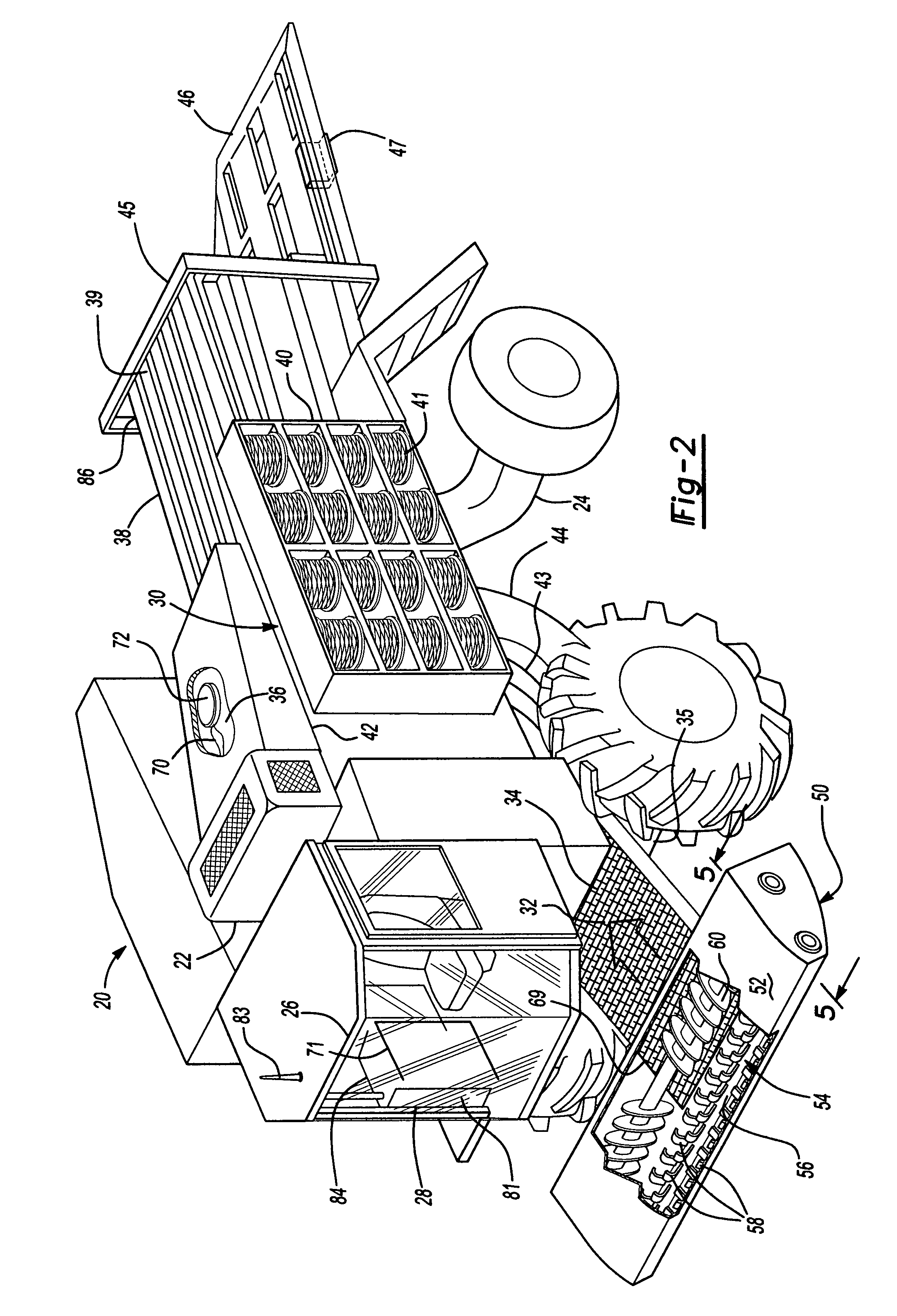
[0024]For purposes of description herein, the terms “upper”, “lower”, “left”, “rear”, “right”, “front”, “vertical”, “horizontal”, and derivatives thereof shall relate to the invention as oriented in FIG. 2. However, it is to be understood that the invention may assume various alternative orientations and step sequences, except where expressly specified to the contrary. It is also to be understood that the specific devices and processes illustrated in the attached drawings, and described in the following specification, are simply exemplary embodiments of the inventive concepts defined in the appended claims. Hence, specific dimensions and other physical characteristics relating to the embodiments disclosed herein are not to be considered as limiting, unless the claims expressly state otherwise.

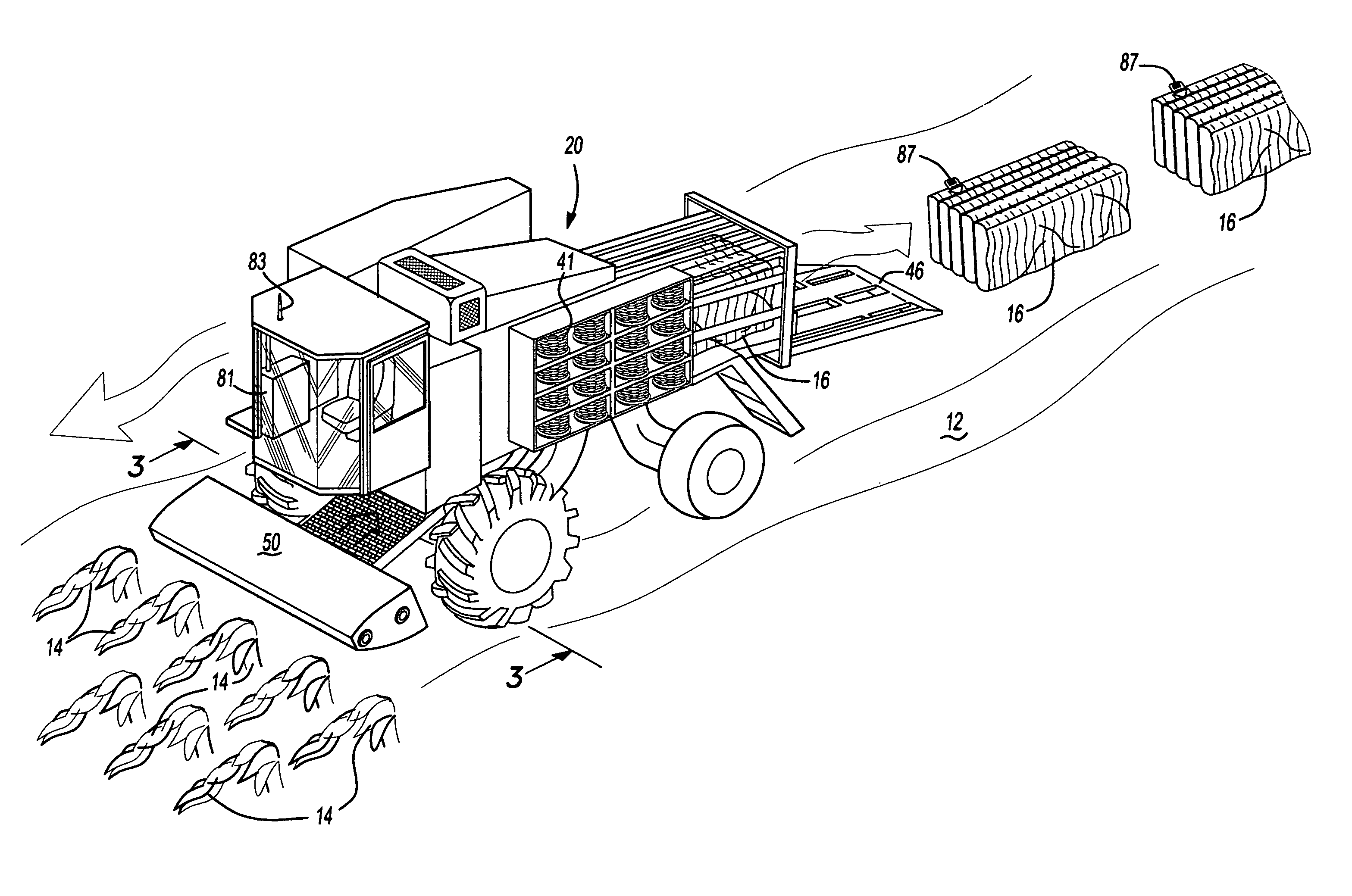
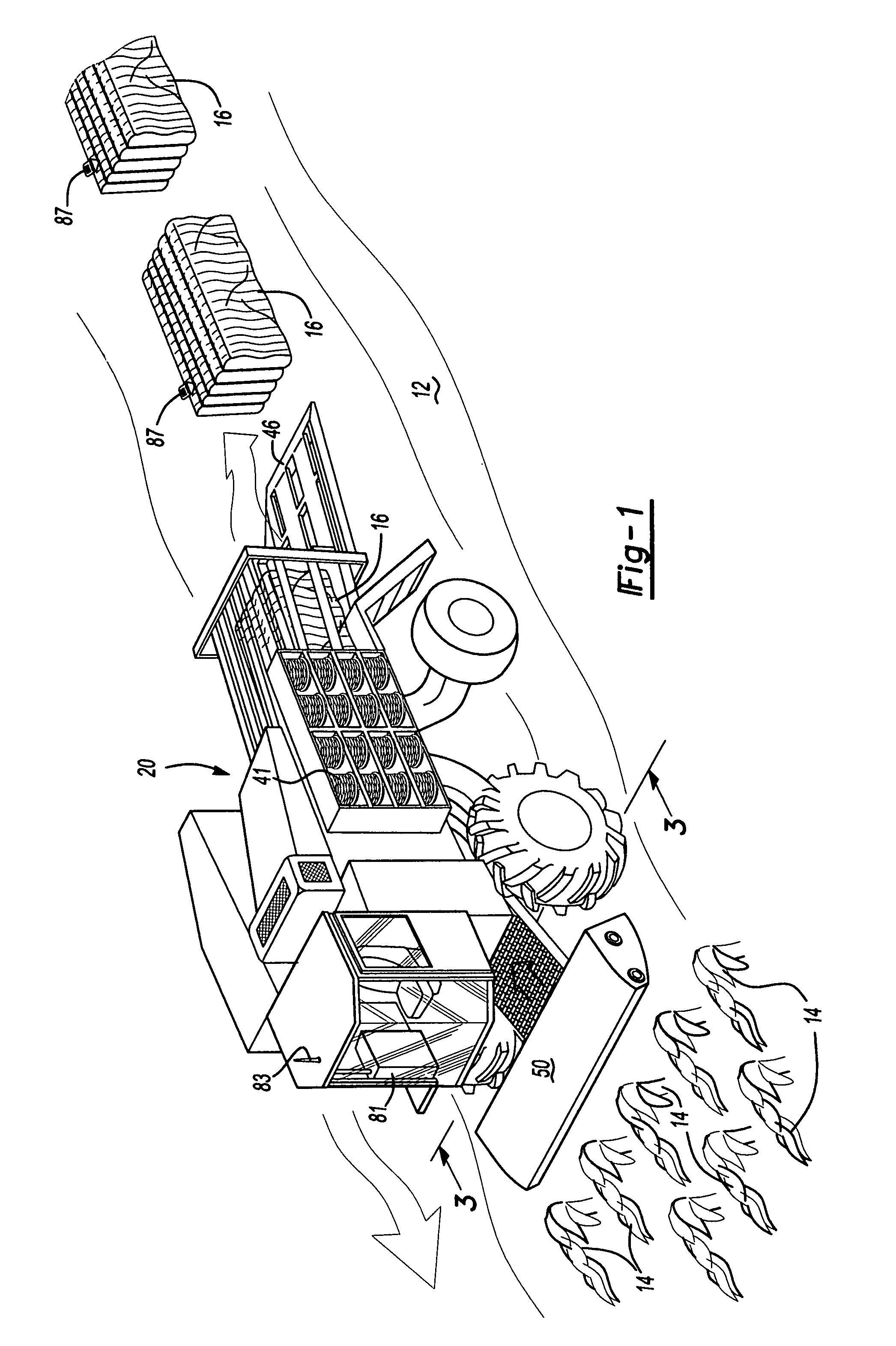
[0025]Turning to the drawings, FIG. 1 shows a biomass harvesting system 20 which is one of the preferred embodiments of the present invention and illustrates its various components. Biomass har...


PUM


Abstract

A biomass harvesting system for harvesting agricultural plant growth from agricultural fields comprises in operative combination a power source for providing mechanical and electric power to the system, a biomass accumulator for producing discrete units of accumulated biomass and a windrower for feeding biomass to the biomass accumulator. The system also includes a biomass quality analyzer for determining a set of quality characteristics of the accumulated biomass, a dirt control system for controlling the quantity of dirt in the accumulated biomass, and a ground cover residue monitor for determining on optimal quantity of biomass residue to remain on the agricultural field. An active tracking system identifies individual ones of the discrete units of accumulated biomass.

Description

CROSS REFERENCE TO RELATED APPLICATIONS[0001]This application claims the benefit of U.S. Provisional Patent Application Ser. No. 60 / 818,988, filed 5 Jul. 2006.BACKGROUND OF THE INVENTION[0002]1. Field of the Invention[0003]The present invention relates to agricultural harvesting systems in general and more particularly to a system for the selective collection of plant growth commonly known as biomass.[0004]2. Discussion of the Related Art[0005]In recent years our society and the world in general has become increasingly more and more energy dependent. The resulting rise in energy demands have coupled with rising costs for petroleum based fuels to kindle an increased interest in alternative fuels that once may have been considered too costly to produce. Of particular interest are fuel sources that are considered to be ‘renewable.’ One of these renewable and alternative energy sources is commonly referred to as biomass.[0006]Biomass generally includes living and recently dead biologica...

Claims


Application Information

Patent Timeline
IPC IPC(8): A01D41/14A01D39/00
CPCA01D37/00A01D41/127A01D91/04A01F15/12A01D75/187
Inventor CROSBY, LON OWEN
Owner CROSBY LON OWEN
Learn More