Hand-held power tool

a power tool and hand-held technology, applied in the field of hand-held power tools, can solve the problems of manufacturing costs, achieve the effects of reducing impact energy, adequate grip, and annihilating a portion of impact energy

Active Publication Date: 2011-02-01
HILTI AG
View PDF19 Cites 11 Cited by
  • Summary
  • Abstract
  • Description
  • Claims
  • Application Information

AI Technical Summary

Benefits of technology

[0010]The support member of the handle itself should not provide for compensation of high impact forces, which noticeably extends their service life and noticeably reduces manufacturing costs of the handle.
[0011]Advantageously, the radial extension of the damping body corresponds to about 1.05 times the 1.8 times, particularly advantageously to about from 1.2 to 1.5 times of the radial extension of the handle at its free, second end. This ensures that the damping body has a sufficiently large, radial and circumferential, easily deformable bead-shaped section.
[0013]Advantageously, the grip sleeve is formed of nitrilebutyl rubber (NBR). Alternatively, natural rubber (NR) or polyamide (PA) can be used for forming the grip sleeve. Upon the power tool falling down, a portion of the remaining, still available impact energy is absorbed by the support member of the handle and a portion of the grip sleeve between the damping body at the free end of the handle and the free end of the support member. Thereby, the damping arrangement is provided with a further stage that further reduces the impact energy which is absorbed in the interior of the power tool.
[0014]Advantageously, the grip sleeve is formed of two materials, with a material adjacent to the support member having a smaller elasticity than a material remote from the support member. E.g., if the material adjacent to the support member is a hard plastic material ensuring the stability of the grip sleeve, and the material remote from the support member is of soft plastic material, an adequate grip is ensured. The materials are chosen of such quality that they can deform under load and thereby once again annihilate a portion of the impact energy.
[0015]Advantageously, each handle is supported for a pivotal movement about a pivot axis defined by a respective handle attachment axle, and the hand-held power tool is further provided with a stop member for limiting pivotal movement of the handle. The stop member is formed of an elastic material. The stop member forms a fourth damping element. Advantageously, the stop member is formed of nitrilebutyl rubber (NBR). The damping sleeve, which is provided between the pivot axis and the mounting section of the handle, forms a first damping element. The stop member forms a further damping element for eliminating impact forces, ensuring an advantageous fall protection of the power tool. The pivotal movement provides for effective vibration damping. Simultaneously, the damping sleeve can absorb the increased impact energy.
[0016]Advantageously, each handle has a radially projecting collar, and an insert formed of an elastic material is provided between the outer housing and the collar and forms a fifth damping element. Advantageously, the insert is formed of nitrilebutyl rubber (NBR). The insert additionally improves the damping characteristics of the multistage damping arrangement.

Problems solved by technology

The support member of the handle itself should not provide for compensation of high impact forces, which noticeably extends their service life and noticeably reduces manufacturing costs of the handle.

Method used


Image

  • Hand-held power tool
  • Hand-held power tool
  • Hand-held power tool

Examples


Embodiment Construction

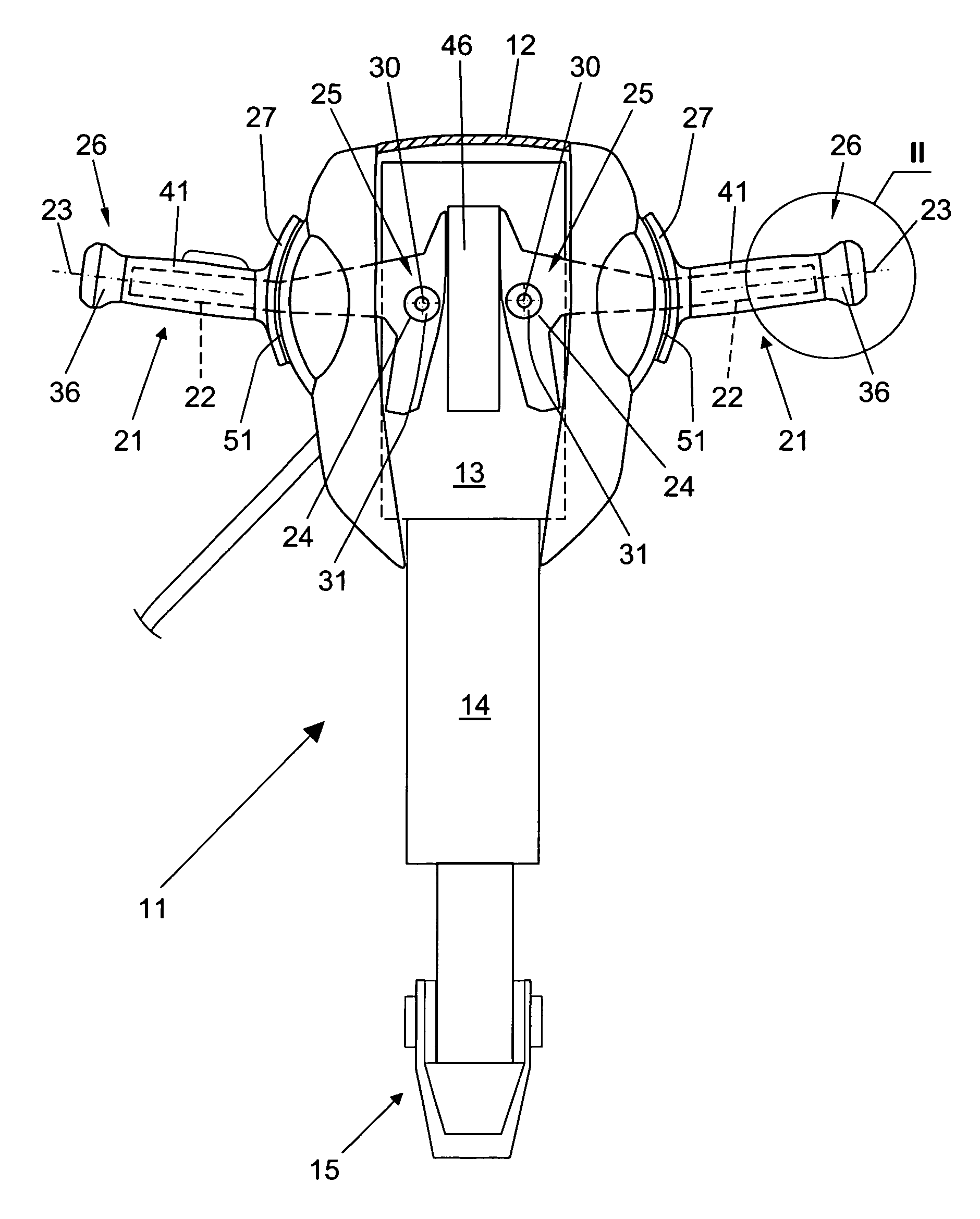
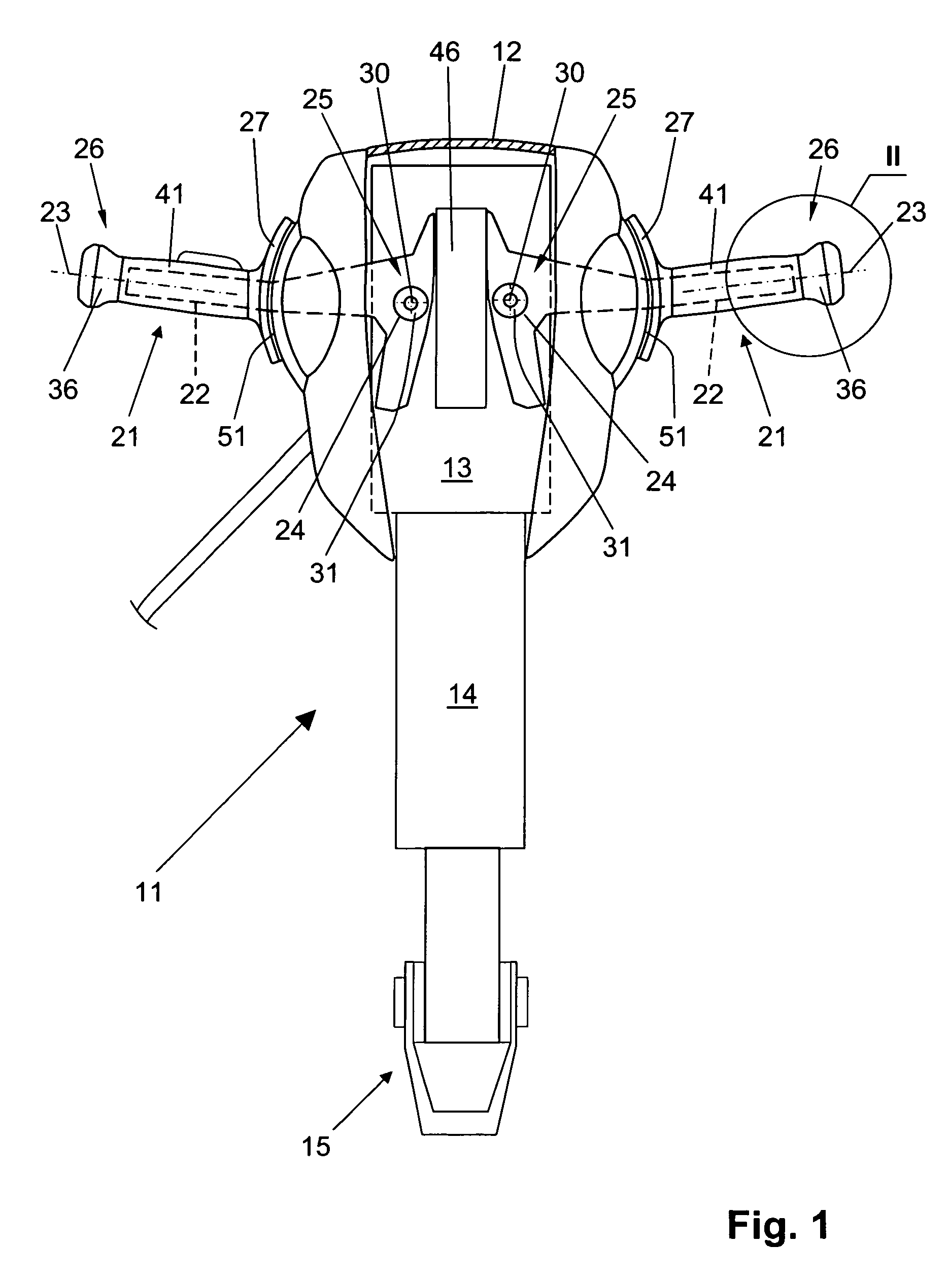
[0022]A hand-held power tool 11, which is formed as a heavy chisel hammer and is shown in FIGS. 1-2, has an outer housing 12, a drive 13, a percussion mechanism 14, and two vibration-damped handles 21. The drive 13 includes, e.g., a motor and a gear unit for driving the percussion mechanism 14. At the free end of the percussion mechanism 14, there is provided a tool holder 15 for a working tool, not shown.

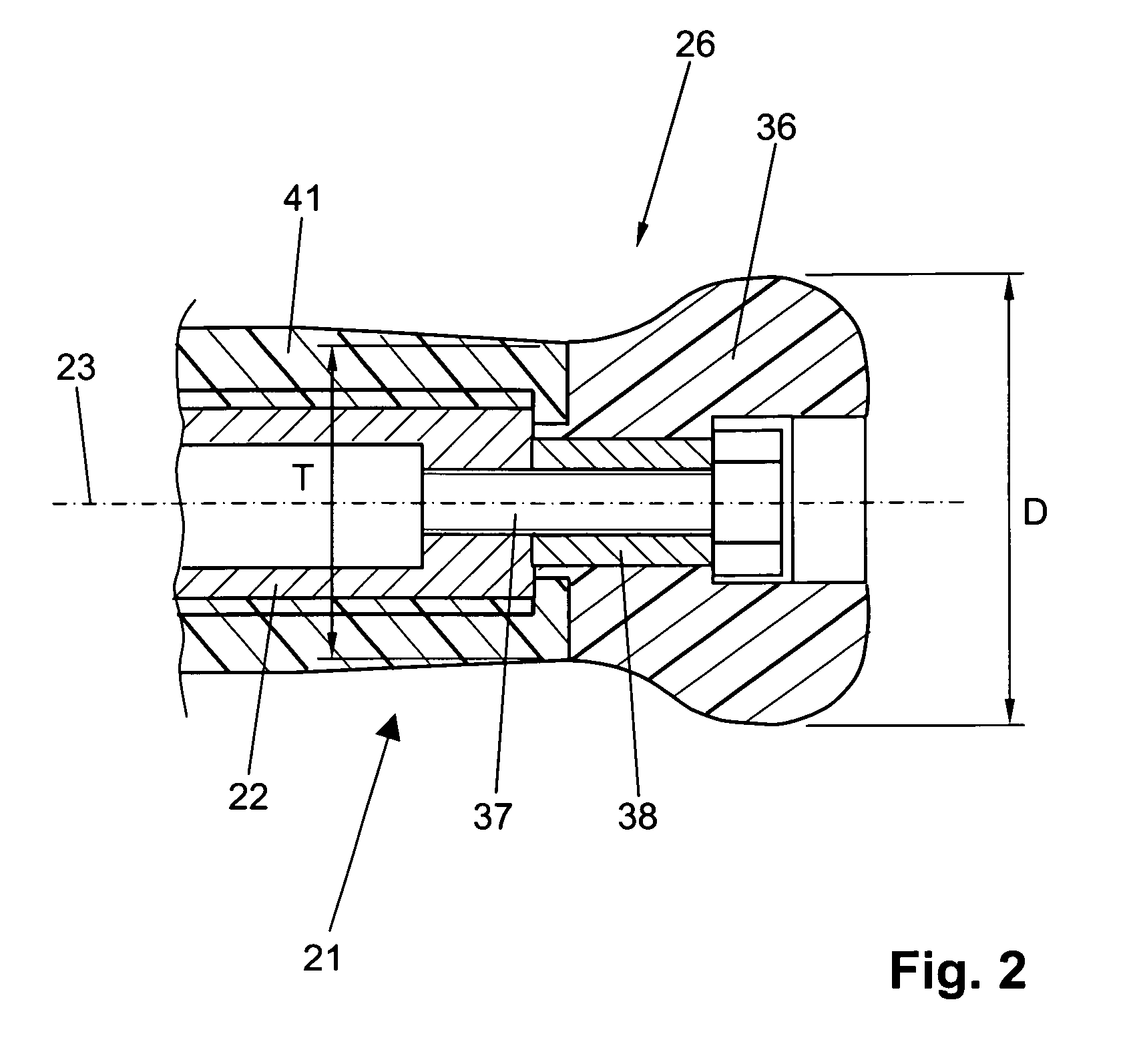
[0023]Each handle 21 has a support member 22 which is formed of steel, a longitudinal axis 23, and a mounting section 24 provided in the first end region 25 of the handle 21. In the hand-held power tool 11, there are provided two handle attachment axles 30 which extend transverse to the longitudinal axes of respective handles 21, parallel to each other, and are surrounded by respective mounting sections 24 of the respective handles 21. The handles 21 are supported for pivotal movement about respective pivot axes which are defined by respective handle attachment axles 30. Between th...


PUM

PropertyMeasurementUnit
angleaaaaaaaaaa
elasticaaaaaaaaaa
elasticityaaaaaaaaaa

Abstract

A hand-held power tool includes two vibration-damped handles (21), two handle attachment axles (31) for securing the two handles (21) on the tool outer housing (12), respectively, and extending at an angle to respective longitudinal axes (23) of respective handles (21), each handle attachment axle being surrounded, at least in some areas, by the mounting section (24) of the respective handle (21), a damping sleeve (31) formed of an elastic material and provided between the mounting section (24) of the respective handle (21) and the respective handle attachment axle (30), with the damping sleeve (31) forming a first damping element, and a damping body (36) provided on a free end (26) of each handle (21) and forming a second damping element and having an extension (D) in a radial, with respect to the handle longitudinal axis, direction that is greater than a minimal radial extension (T) of the handle (21) at its free, second end.

Description

BACKGROUND OF THE INVENTION[0001]1. Field of the Invention[0002]The present invention relates to a hand-held power tool including an outer hosing, a percussion mechanism, a motor for driving the percussion mechanism, two vibration-damped handles each having a support member, a longitudinal axis, and a mounting section provided at a first end region of the handle, two handle attachment axles for securing the two handles on the outer housing, respectively, and extending at an angle to respective longitudinal axes of respective handles, with each handle attachment axle being surrounded, at least in some areas, by the mounting section of a respective handle, and a damping sleeve formed of an elastic material and provided between the mounting section of the respective handle and the respective handle attachment axle, with the damping sleeve forming a first damping element.[0003]2. Description of the Prior Art[0004]Large hand-held power tools with a percussion mechanism such as, e.g., hea...

Claims


Application Information

Patent Timeline
Patent Type & Authority Patents(United States)
IPC IPC(8): B25F5/02
CPCB25D17/043B25D17/24B25F5/006B25F5/026B25D2222/42B25D2222/57B25D2222/61B25D2250/275
Inventor KOCH, OLAFBUCHENAU, ALEXANDERNUEBEL, VERAPLANK, UTOHAMMERSTINGL, STEFAN
Owner HILTI AG
Why Eureka
Try Eureka