Illumination device

a technology of a slit and a tube is applied in the field of slit devices, which can solve the problems of difficulty in obtaining a radiation characteristic that is uniform in color and intensity, and devise a flat construction, and achieve the effect of being particularly efficient and lightweigh

Inactive Publication Date: 2011-02-01
OSRAM OPTO SEMICONDUCTORS GMBH
View PDF43 Cites 14 Cited by
  • Summary
  • Abstract
  • Description
  • Claims
  • Application Information

AI Technical Summary

Benefits of technology

The light sources of a light source group are preferably all disposed on a common carrier. As a general rule, this makes it possible to simplify process flows during production. The production and assembly of the light sources can thus be simplified, since modules containing-one light source group can each be fabricated on a carrier in a first production step and subsequently built up into an illumination device, for example by mounting them on an additional carrier corresponding to the provided first regular grid.
Organic light-emitting diodes (OLEDs), inorganic semiconductor light-emitting diodes (LEDs) or laser diodes (LDs) are preferably used as light sources in the illumination device. Such light sources generally have the advantages of high efficiency, low energy consumption and small construction.

Problems solved by technology

However, with illumination devices of this design, it is particularly difficult to obtain a radiation characteristic that is uniform in terms of color and intensity and at the same time devise a flat construction.

Method used


Image

  • Illumination device
  • Illumination device
  • Illumination device

Examples


Embodiment Construction

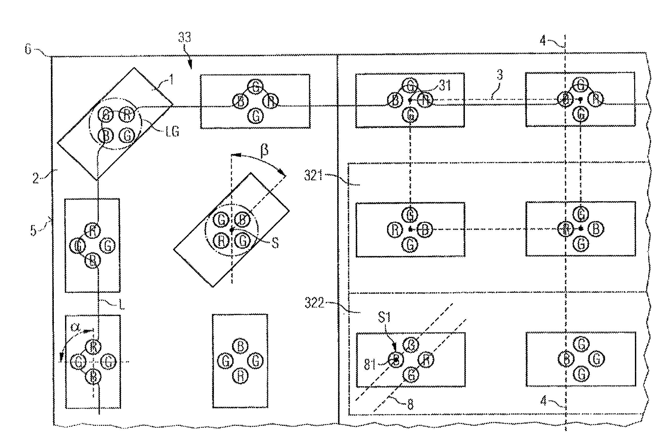
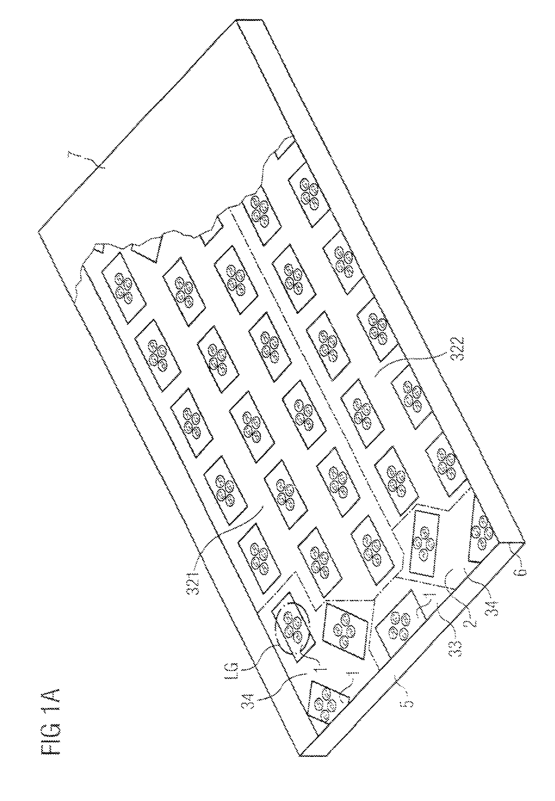
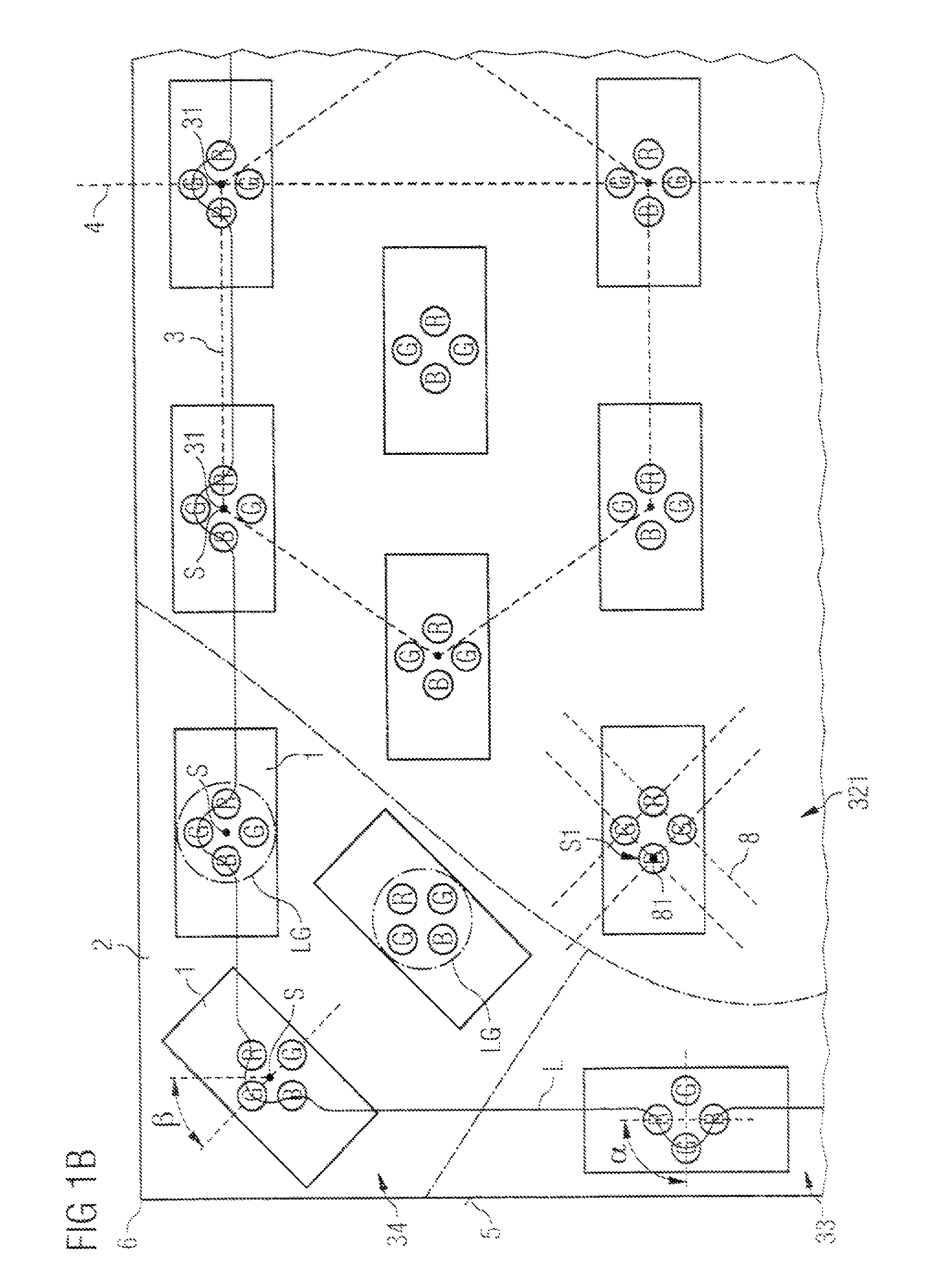
In the exemplary embodiments and figures, like or like-acting elements are provided with the same respective reference numerals. The illustrated elements and their size relationships are basically not to be considered true to scale, but rather, individual elements, such as for example light sources or light source groups and grid structures, may be depicted as exaggeratedly large for the sake of better understanding and / or better visualization.

The illumination device according to the exemplary embodiment of FIGS. 1A and 1B comprises a multiplicity of light sources. The light sources used in the present case are light-emitting diodes (“LEDs” for short). However, other light sources can also be used, for example organic light-emitting diodes or laser diodes.

The multiplicity of LEDs comprises LEDs that emit red light (hereinafter “red LEDs”) LEDs that emit green light (hereinafter “green LEDs”), and LEDs that emit blue light (hereinafter “blue LEDs”). Red LEDs, green LEDs and blue LEDs...


PUM


Abstract

Disclosed is an illumination device comprising a radiation-emitting front side and a multiplicity of light sources (R, G, B), wherein said multiplicity of light sources (R, G, B) is divided into light source groups (LG) and the light source groups (LG) are arranged on the grid points of a first regular grid.

Description

CROSS-REFERENCE TO RELATED APPLICATIONSThis application is the National Stage of international Application No. PCT / DE2006 / 000082, filed on Jan. 19, 2006, which claims the priority to German Patent Applications Ser. No. 10 2005002709.1, filed on Jan. 19, 2005, Ser. No. 10 2005060382.3, filed on Dec. 16, 2005 and Ser. No. 10 2006002275.0, filed on Jan. 17, 2006. The contents of all applications are hereby incorporated by reference in their entireties.FIELD OF THE INVENTIONThe invention relates to an illumination device having a radiation-emitting front side and a multiplicity of light sources divided into light source groups.BACKGROUNDAn illumination device for the backlighting of displays is described for example in the document WO 2004 / 031844 A1. To generate light that creates a white color impression, that illumination device comprises individual colored light sources arranged such that mixed-color light is radiated from the front side of the illumination device. In addition, in th...

Claims


Application Information

Patent Timeline
Patent Type & Authority Patents(United States)
IPC IPC(8): F21V9/00F21K99/00
CPCF21K9/00G02F1/133603F21Y2105/003G02F2001/133613F21Y2105/12F21Y2105/10G02F1/133613F21Y2113/13
Inventor BLUMEL, SIMONOTT, HUBERTPLOTZ, LUDWIGWANNINGER, MARIOKIRCHBERGER, GUNTERWOLFF, PETERZEILER, MARKUS
Owner OSRAM OPTO SEMICONDUCTORS GMBH
Why Eureka
Try Eureka