
Generating nonlinear FM chirp radar signals by multiple integrations

a technology of chirp radar and multi-integration, which is applied in the direction of reradiation, measurement devices, instruments, etc., can solve the problems of reducing output snr as well, affecting the design of chirp radar, and affecting etc., and achieves the effect of improving the quality of chirp radar, reducing the cost of chirp radar, and improving the accuracy of chirp radar

Active Publication Date: 2011-02-01
NAT TECH & ENG SOLUTIONS OF SANDIA LLC
View PDF4 Cites 18 Cited by
  • Summary
  • Abstract
  • Description
  • Claims
  • Application Information

AI Technical Summary

Problems solved by technology

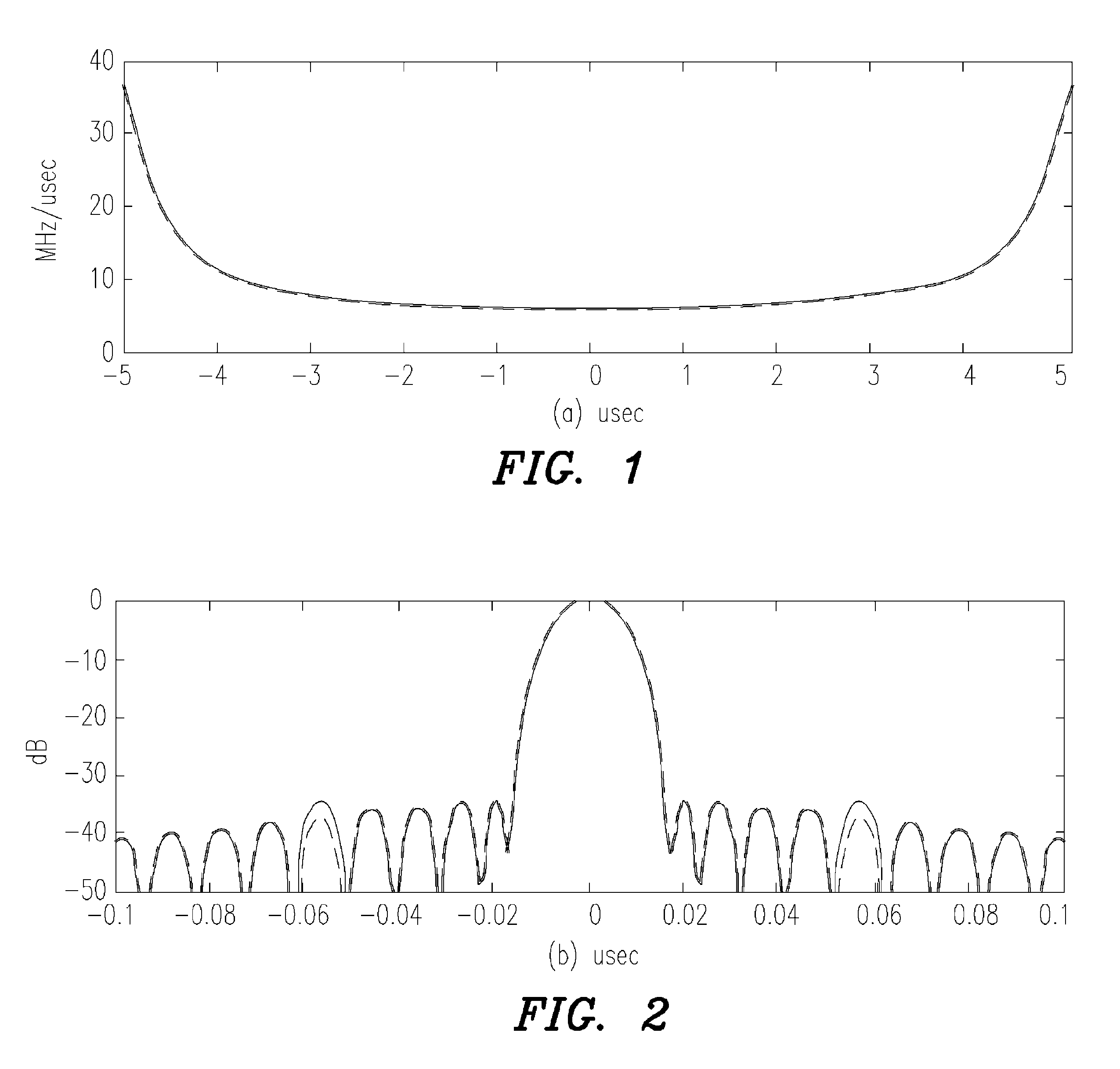
However, since a LFM chirp waveform has nearly a rectangular PSD, its autocorrelation function exhibits a sinc( ) function shape, i.e. sin(x) / x, with its attendant problematic sidelobe structure.
However, since the cumulative filtering is no longer precisely matched to the signal, it necessarily reduces output SNR as well, typically by 1-2 dB (depending on the filtering or weighting function used).
However, precision NLFM chirps are more difficult to design, produce, and process than LFM chirps.
Alternatives to NLFM modulation for shaping the PSD, such as amplitude tapering the transmitted signal, are problematic because efficient power amplification of the waveform typically necessitates operating the hardware in a nonlinear manner, e.g. operating the amplifiers in compression.
This substantially reduces the ability to maintain precision amplitude tapering.
However, the design of NLFM radar chirp waveforms, and the linkage between design and production of those waveforms, remain as challenges in the radar field.

Method used


Image

  • Generating nonlinear FM chirp radar signals by multiple integrations
  • Generating nonlinear FM chirp radar signals by multiple integrations
  • Generating nonlinear FM chirp radar signals by multiple integrations

Examples


Embodiment Construction

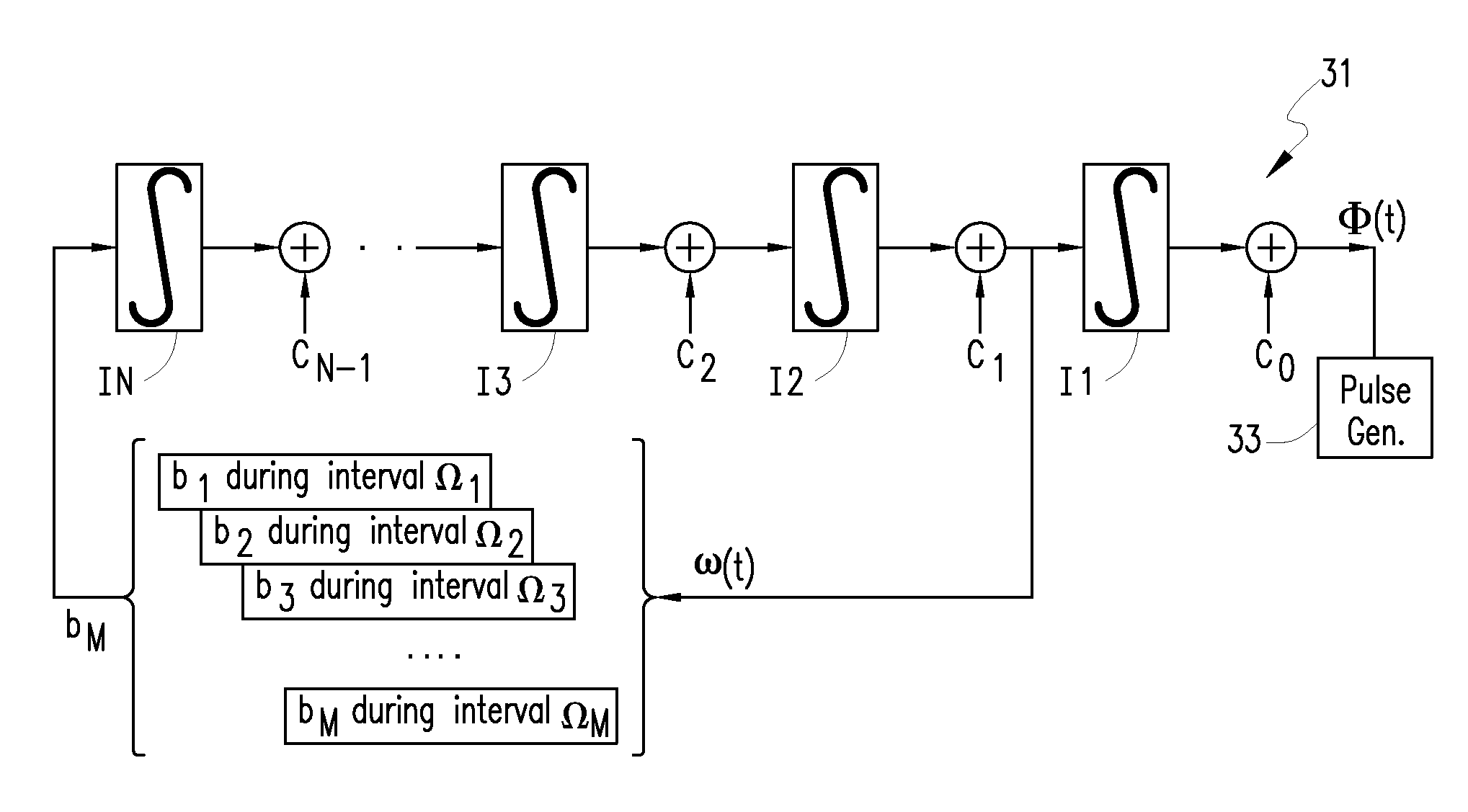
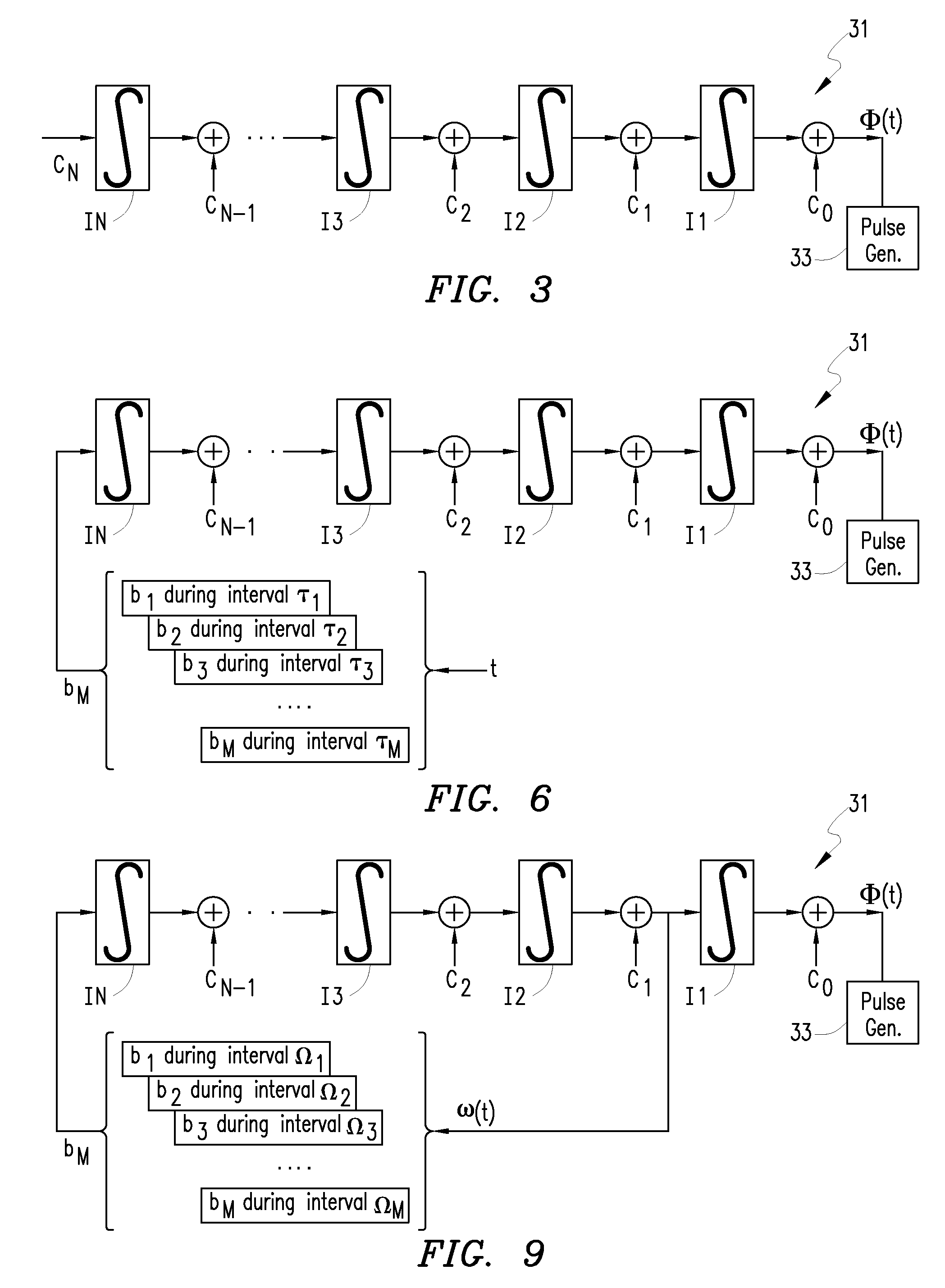
[0019]It is typically advantageous in radar design, as elsewhere, to capture as much of the radar system's performance capability as possible. A single dB of additional SNR gained elsewhere is equivalent to a 25% increase in transmitter power. Alternatively, a single dB of additional SNR can have dramatic effects in reducing false alarm rates in target detection applications. Exemplary embodiments of the invention create NLFM chirp radar waveforms with characteristics that can avoid the aforementioned 1-2 dB of SNR degradation that is typically associated with sidelobe filtering in LFM chirp approaches. In various embodiments, a suitable NLFM chirp radar waveform is produced by using a cascaded digital integration structure, as described in detail hereinbelow.

[0020]The present invention is applicable to radar signals with relatively large time-bandwidth products, which are typical in conventional high-performance radar systems. Rayleigh energy criteria infer that for an LFM chirp of...


PUM


Abstract

A phase component of a nonlinear frequency modulated (NLFM) chirp radar pulse can be produced by performing digital integration operations over a time interval defined by the pulse width. Each digital integration operation includes applying to a respectively corresponding input parameter value a respectively corresponding number of instances of digital integration.

Description

[0001]This invention was developed under Contract DE-AC04-94AL85000 between Sandia Corporation and the U.S. Department of Energy. The U.S. Government has certain rights in this invention.FIELD OF THE INVENTION[0002]The invention relates generally to generating chirp radar signals and, more particularly, chirp radar signals with a non-linear chirp.BACKGROUND OF THE INVENTION[0003]It is well known that when a signal is input to a matched filter (matched to the input signal) then the output of the filter is the autocorrelation function of the signal. Also well known is that the autocorrelation function is the Fourier transform of the signal's power spectral density (PSD). A matched filter provides optimum (maximum) signal-to-noise ratio (SNR) at the peak of its autocorrelation function, and is consequently optimum for detecting the signal in noise.[0004]A very common conventional radar waveform is the Linear FM (LFM) chirp signal. Such a signal can be readily generated by a variety of ...

Claims


Application Information

Patent Timeline
Patent Type & Authority Patents(United States)
IPC IPC(8): G01S13/00
CPCG01S7/282G01S13/282
Inventor DOERRY, ARMIN W.
Owner NAT TECH & ENG SOLUTIONS OF SANDIA LLC
Learn More