Sync mark detection with polarity uncertainty

a data storage system and polarity uncertainty technology, applied in the field of systems and methods for detecting data, can solve problems such as partial erasure, dropout, and reduced overall system performance, and achieve the effect of reducing overall system performance, reducing and increasing the number of data readout bits

Inactive Publication Date: 2011-02-01
MARVELL TECHNOLOGY GROUP LTD
View PDF2 Cites 17 Cited by
  • Summary
  • Abstract
  • Description
  • Claims
  • Application Information

AI Technical Summary

Benefits of technology

[0013]As mentioned, selecting the tolerance threshold to use in the comparisons may require determining the polarity of the read head while reading the previous disk sector. Since the polarity of the read head may not be known while reading a particular disk sector, the polarity may be determined once the disk...

Problems solved by technology

If the disk read mechanism needs to re-read the disk often, the throughput of the disk read channel may suffer, causing a decrease in overall system performance.
For example, as data densities and data rates increase, sources of error in magnetic data storage channels including media noise, electronics and head noise, inter-track interference, thermal asperity, partial erasure, and dropouts, become more pronounced.
Thus, the data storage system may not know wh...

Method used


Image

  • Sync mark detection with polarity uncertainty
  • Sync mark detection with polarity uncertainty
  • Sync mark detection with polarity uncertainty

Examples


Embodiment Construction

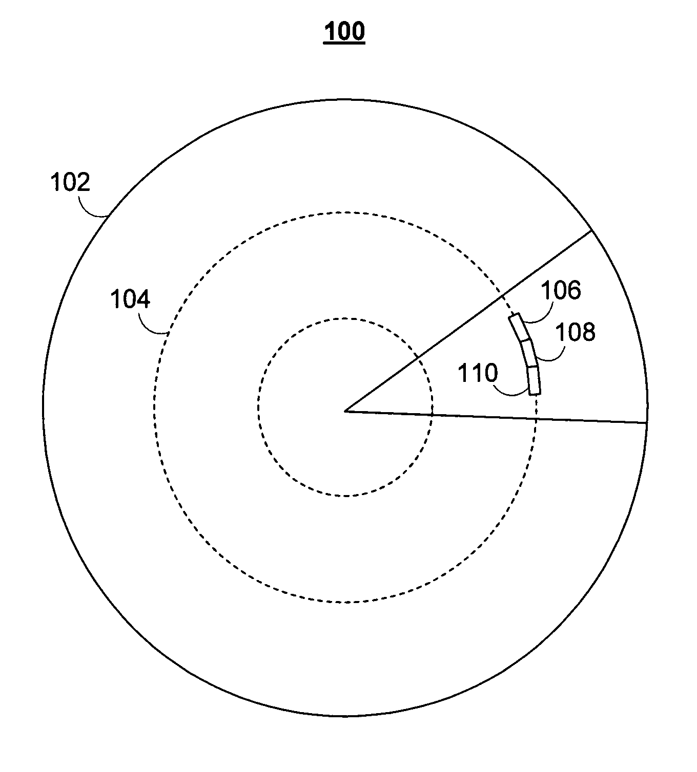
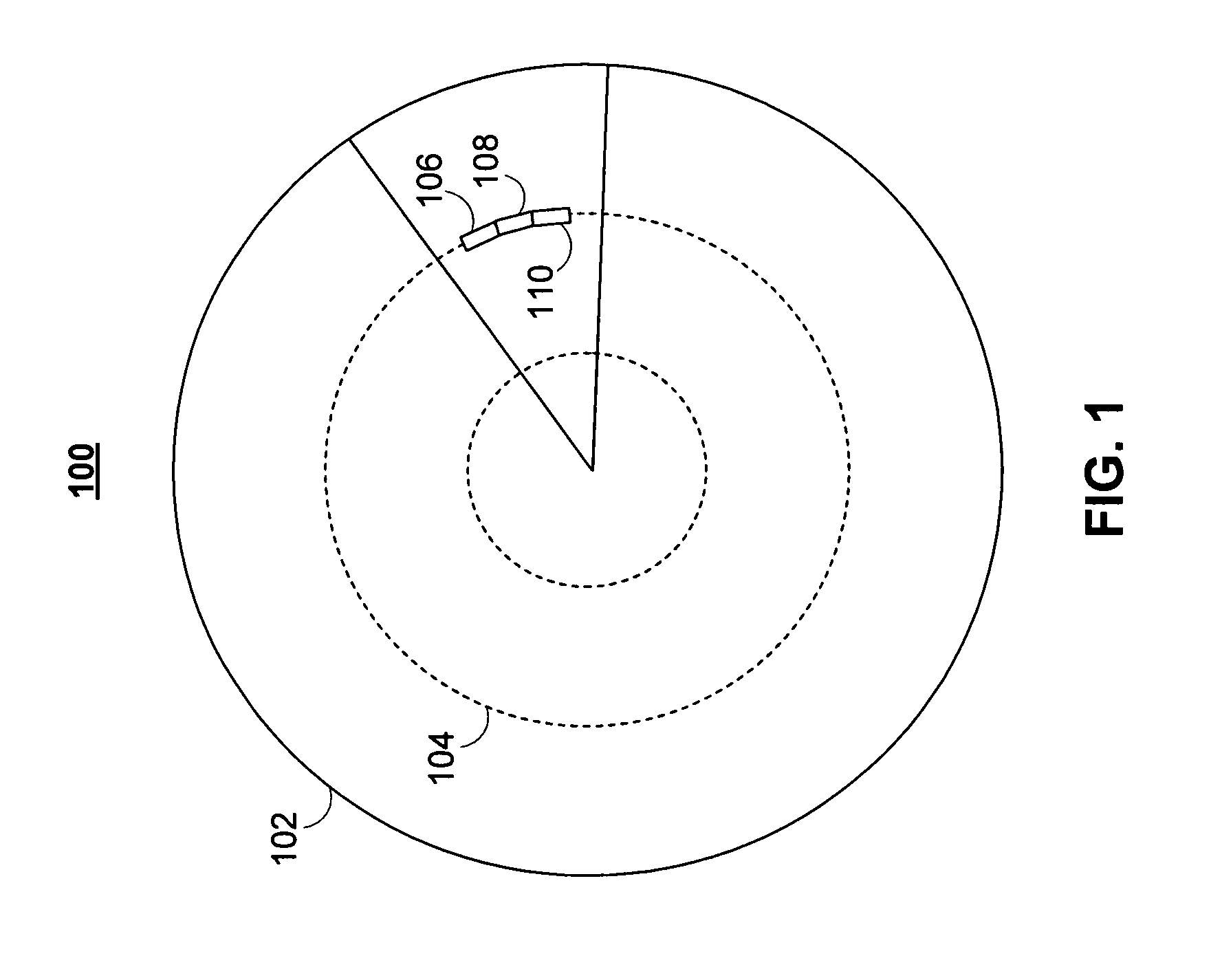
[0031]FIG. 1 shows illustrative hard disk 100 in accordance with one embodiment of the present invention. Disk platter 102 may contain numerous concentric data tracks, such as track 104. These tracks may be divided into sectors, with each sector including sector preamble 106, sector sync mark 108, and user data 110.

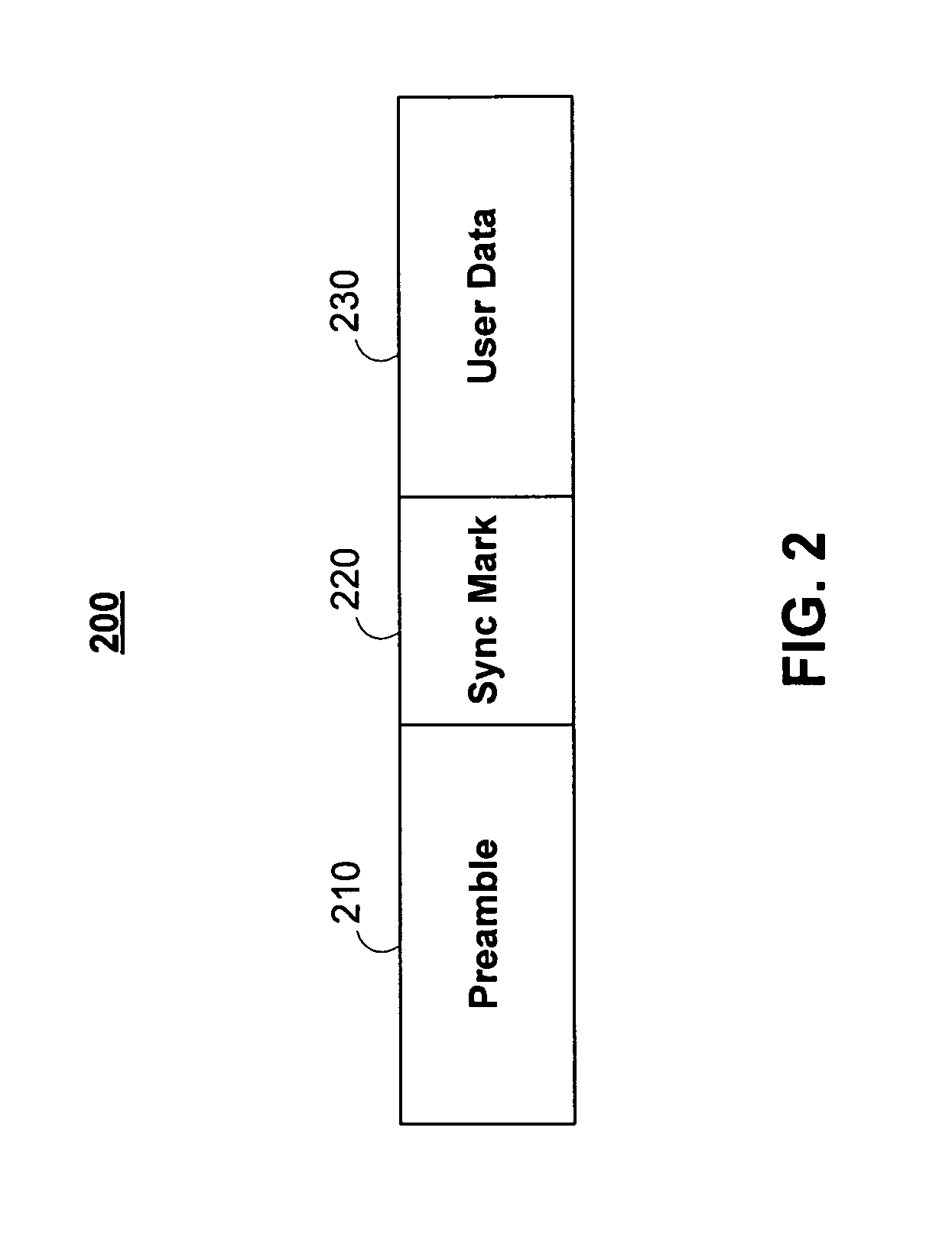
[0032]FIG. 2 shows illustrative disk sector 200 in accordance with one embodiment of the invention. Disk sector 200 may include preamble 210. Preamble 210 of disk sector 200 may, for example, contain a pattern of bits that enables the disk read channel to calibrate its gain and allows the read channel to achieve bit synchronization. Gain calibration may be achieved with automatic gain control (AGC) circuitry, and bit synchronization may be achieved with phase locked loop (PLL) circuitry (not shown). The pattern of bits may be repeated a number of times, for example 30, 35, 40, or more than 40 times. In addition, the preamble may be a 2T pattern, such as ‘1100’, where T is...


PUM


Abstract

Systems and methods for detecting a disk sync mark are provided. The systems and methods for detecting the disk sync mark rely on a detecting the disk sync mark on at least one timing interval. A window of data read bits from a particular disk sector are examined to determine whether they match the disk sync mark. The disk sync mark may be differentiated from expected versions of the disk sync mark using a calculated set of thresholds.

Description

CROSS REFERENCE TO RELATED APPLICATIONS[0001]This claims the benefit of copending, commonly-assigned U.S. Provisional Patent Application No. 60 / 827,780 filed Oct. 2, 2006, which is hereby incorporated by reference herein in its entirety.BACKGROUND OF THE INVENTION[0002]Embodiments of the invention generally pertain to systems and methods for detecting data on a machine-readable storage medium. In particular, embodiments of the invention pertain to systems and methods for detecting a sync mark for data in a data storage system.[0003]Typically, data is stored on magnetic hard disk drives in concentric tracks on the recording surface or surfaces of the disk or disks. Each track may be divided into a number of addressable sectors, with each sector including a preamble, sync mark, and user data.[0004]The preamble of a disk sector may, for example, contain a pattern of bits that enables the disk read channel to calibrate its gain and allows the read channel to achieve bit synchronization....

Claims


Application Information

Patent Timeline
IPC IPC(8): G11B7/00G11B5/09G11B20/10G11B5/035
CPCG11B5/09G11B5/59616G11B20/10009G11B20/10222G11B2020/1232G11B2020/1287G11B2220/2516
Inventor HAN, KEWU, ZINING
Owner MARVELL TECHNOLOGY GROUP LTD
Why Eureka
Try Eureka