Disposable dental applicator

a technology of applicators and brushes, applied in the field of disposable applicators, can solve the problems of difficult manipulation and placement of brushes on the handle, not without inconvenience, and the brush end that attaches to the handle is relatively small, and achieves the effects of dense simple and inexpensive, and enhanced uniform distribution of flocking material

Inactive Publication Date: 2011-02-08
CENTRIX
View PDF51 Cites 18 Cited by
  • Summary
  • Abstract
  • Description
  • Claims
  • Application Information

AI Technical Summary

Benefits of technology

[0006]Another object is to provide for a simple and inexpensive applicator having a handle with a brush applicating end portion on one end of the handle and a flocked applicating end portion on the other end of the handle with a frangible portion disposed intermediately of the respective ends of the handle.
[0007]Another object is to provide an applicator having an end portion formed of various shapes to enhance a more uniform distribution of flocking material to the end portion of a handle.
[0009]Another object is to provide an applicator having an end portion with enhanced surface area so as to catch and hold the adhesive applied thereto and thereby creating a more favorable environment for effecting a more uniform and dense distribution of the flocking material thereto.
[0010]The foregoing objects and other features and advantages are attained by an applicator having an elongated handle with one end formed for receiving a tuft of bristles to define a brush applicating end and having its other end shaped to maximize the surface area thereof for effecting a more dense and uniform distribution of the flocking material thereto. Also, the applicator of this invention may be provided with a handle formed with a tufted brush at each end thereof, or with a flocked applicating end at each end thereof. With such double ended applicator, there is also provided intermediate the opposed ends of the handle a frangible portion defined as a V-shaped groove circumscribing the handle so as to facilitate the severing of the handle at the defined frangible portion to render the integrally formed double ended applicator into two separate and distinct single ended applicator. One or both ends of the applicator may be provided with an applicator formed of a tuft of bristles to define a brush end or may be coated with a flocking material to define a flocked end. The opposed end portions of the handle adjacent the respective applicating ends are formed so that the applicating end portions or end applicators may be readily bent at an angle relative to the longitudinal axis of the handle.
[0011]In accordance with this invention, the applicating end portion of the handle receiving the flocking material is formed so that the surface area thereof is enhanced either by forming the applicating end portion with one or more grooves to increase the surface area thereat, or the applicating end portion may be provided with a series of dimples or depressions to increase the surface area thereof. This arrangement functions to catch and hold the applied adhesive to form a mechanical bond and to which the flocking material can be more uniformly adhered to provide for a more densely flocked applicating end portion capable of retaining a greater amount of material to be applied to a tooth or other surface.

Problems solved by technology

While this brush configuration has been adequate, it is not without some inconveniences.
For example, the brush end that attaches to the handle is relatively small and difficult to manipulate and place on the handle.
This is especially difficult when a dentist is wearing gloves.
This compromises the use of the attached handle portion in that it must be disinfected.
However, it has been observed that due to the limited amount of surface area located at the end of the applicator handle, the amount of flocking fibers that would normally adhere thereto utilizing the teaching of said German patent was quite limited.

Method used


Image

  • Disposable dental applicator
  • Disposable dental applicator
  • Disposable dental applicator

Examples


Embodiment Construction

[0025]This invention relates to a double ended applicator which is particularly adapted for use in the dental profession, although not limited thereto, of the type initially disclosed in a co-pending application Ser. No. 08 / 934,983 filed Sep. 22, 1997, for Disposable Dental Applicator. This application, being a continuation-in-part of said co-pending application Ser. No. 08 / 934,983, now U.S. Pat. No. 6,049,934, incorporates said co-pending application Ser. No. 08 / 934,983 herein by reference.

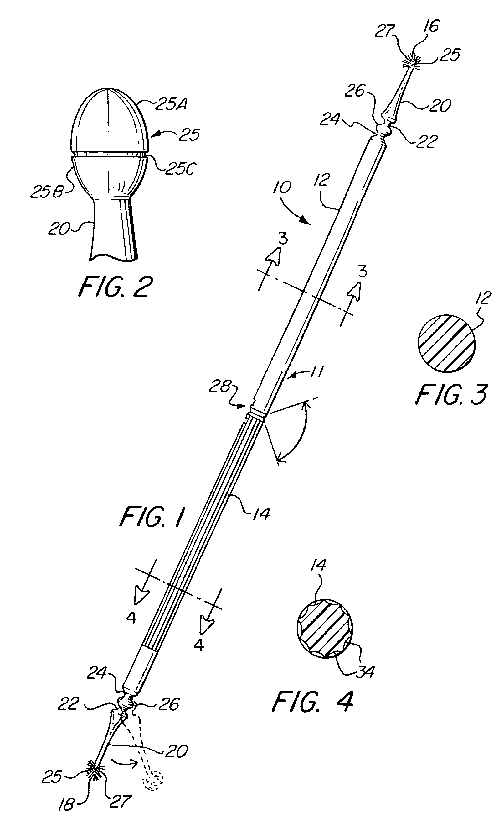
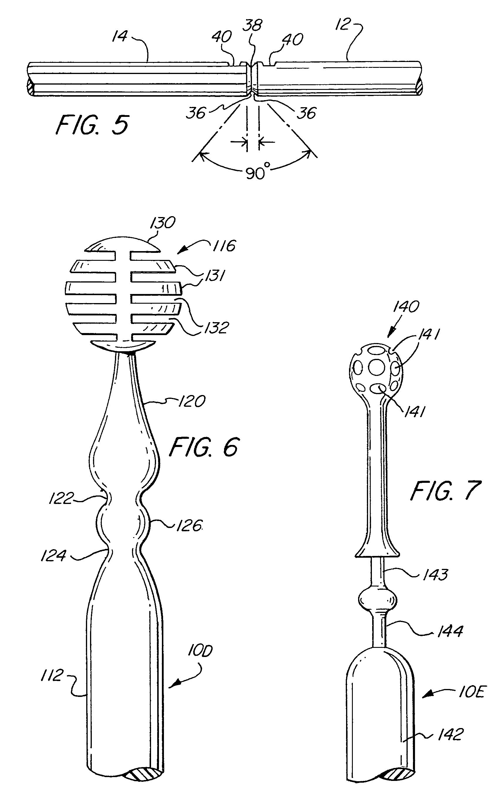
[0026]Referring to the drawings, there is shown in FIG. 1 one embodiment of the invention. As shown, the applicator 10 includes an elongated handle 11 having opposed applicating end portions 16 and 18 and a frangible means in the form of a circumscribing groove 28 disposed intermediate the opposed ends 16 and 18. The arrangement is such that the elongated handle 11 includes handle sections 12 and 14 which are connected by the frangible means or groove 28.

[0027]In the form of the invention illustr...


PUM


Abstract

An applicator principally for use in the dental profession, for the placement of different materials as may be required. The applicator includes an elongated handle having an applicating end portion formed at the opposed ends thereof which may be either of like or unlike construction, i.e. formed as a brush and / or a flocked applicating end portion. The flock may extend from the distal end a predetermined longitudinal distance over an extended portion. Intermediate the opposed applicating end portion, the elongated handle is provided with a circumscribing groove to define a frangible area by which the user, at his or her option, can cleanly sever the applicator handle to form two separate and distinct applicators. The applicator is also provided with a hinging arrangement adjacent the opposed applicating end portions whereby the applicating end portions may be angularly bent relative to the elongated handle at the option of the user.

Description

RELATED APPLICATIONS[0001]This application is a continuation application of application Ser. No. 09 / 549,362, filed Apr. 14, 2000, now U.S. Pat. No. 6,634,051, which is a continuation-in-part application of application Ser. No. 08 / 934,983 filed Sep. 22, 1997, now U.S. Pat. No. 6,049,934, and a continuation-in-part application of application Ser. No. 09 / 517,549 filed Mar. 2, 2000, now U.S. Pat. No. 6,186,792, all of which are herein incorporated by reference.FIELD OF INVENTION[0002]The present invention relates to disposable applicators for applying various materials, and more specifically to a double ended disposable dental applicator having either a double ended brush applicating end, or a double ended flocked applicating end, or having a flocked applicator on one end and a brush applicator on the other end.BACKGROUND OF THE INVENTION[0003]Applicators such as brushes, foam pads, cotton swabs or other applicators, are used to apply a variety of materials in many applications. Such ap...

Claims


Application Information

Patent Timeline
Patent Type & Authority Patents(United States)
IPC IPC(8): A46B9/04A46B17/02A46B5/00A61C3/00A61C5/00A61C5/06A61C15/04A61C19/00A61F13/38B05C17/00
CPCA46B5/00A46B5/0016A46B5/0079A61C3/00A61C3/005A61C5/06A46B2200/1046A46B2200/108A61C2201/002A61C5/60
Inventor DRAGAN, WILLIAM B.DISCKO, JOHN J.
Owner CENTRIX
Why Eureka
Try Eureka