Low power, low cost illuminated keyboards and keypads

Inactive Publication Date: 2011-02-08
GOOGLE LLC +1
View PDF25 Cites 4 Cited by
  • Summary
  • Abstract
  • Description
  • Claims
  • Application Information

AI Technical Summary

Benefits of technology

[0004]An object of the present invention is to provide methods for manufacture of illuminated keyboards that can easily be adapted and incorporated into the manufacture processes that exist for non-illuminated keyboards.
[0006]Another object of the present invention is to provide uniform illumination of the keys in a manner that does not require implementation of complex optical pathways or separate light sources for each key, and further provides illumination that consumes very low power.
[0007]Yet another object of the present invention is to provide illumination that possesses controllable visual functionality as well as aesthetic attributes.
[0008]According to one aspect of the present invention a flexible, thin, low power, inexpensive, luminescent sheet is adhered to the surface of the key board well plate of a keyboard. The key board well plate is manufactured in any manner and shape as required by the manufacturing process typically used and as required by the shape of the keyboard to be produced. The luminescent sheet may be adhered to the upper surface of the keyboard well plate. Alternatively, the luminescent sheet may be placed between the keyboard well plate and the circuit board of the keyboard. In this configuration the keyboard well plate is made from any optically transmissive material possessing sufficient rigidity to function as a key board well plate. Such materials, such as plexi-glass and other moldable plastics are well known in the art. The keys are also manufactured as required by the manufacturing process ordinarily used, except that the keys are made from an optically transmissive material, and may further contain phosphorescent material that glows residually during and after illumination. The luminescent sheet may be easily connected to a battery or any available power source, including the source that provides power to the keyboard itself. Further, the luminescent sheet may be connected to a device such as a rheostat to allow the user to vary the intensity of illumination. Also, a photo cell may be connected to the source of power of the luminescent sheet to cause the intensity of light from the sheet to automatically vary in response to the darkness of the environment in which the keyboard is used.
[0009]According to the present invention, luminescent sheets of different colors can be placed under different sections of keys to improve visual differentiation of key groups. Also, the optically transmissive keys can be tinted so that the same luminescent sheets will cause keys tinted by different colors to appear in different colors. Similarly, the top plate of the keyboard which is normally opaque can also be manufactured from an optically transmissive material so that the entire upper surface of the keyboard will be illuminated. The top plate may be tinted to provide visual contrast. Also, one luminescent sheet of one color can be applied to illuminate the top plate with a color that is different from the color of the luminescent sheet that illuminates the keys. All of these features may be combined to provide an illuminated keyboard that possesses controllable visual functionality and aesthetic attributes. Further, the methods of the present invention disclosed herein can be implemented by persons of ordinary skill in the art to convert existing keyboards into illuminated keyboards.

Problems solved by technology

However, difficulty has been encountered in the development of illuminated keyboards that are light weight, low in cost and easy to manufacture.
For example, methods have been developed which require placement of a light source below and in proximity of each key of the keyboard, and each of these light sources must be connected to a power supply, rendering the manufacture of such a keyboard difficult and expensive.
The optical light paths are difficult to construct in order to illuminate the keys uniformly and efficiently.
These methods have the disadvantage of requiring considerable power for illumination, an important consideration for laptop computers and calculators operating under battery power.
Moreover, all of these methods are unsuitable for many of the new keyboards that have been developed which are not flat, such as ergonomic keyboards that arc upward and outward from a horizontal surface.
More generally, none of the methods of the prior art are readily adaptable to existing keyboard manufacturing processes.
Thus, the manufacturing process for manufacturing ordinary non-illuminated keyboards cannot readily and easily be adapted to the manufacture of illuminated keyboards.

Method used


Image

  • Low power, low cost illuminated keyboards and keypads
  • Low power, low cost illuminated keyboards and keypads
  • Low power, low cost illuminated keyboards and keypads

Examples


Embodiment Construction

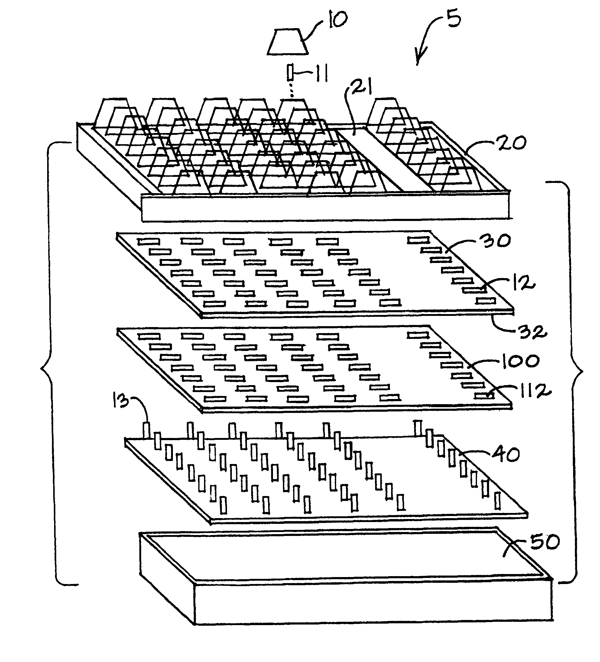
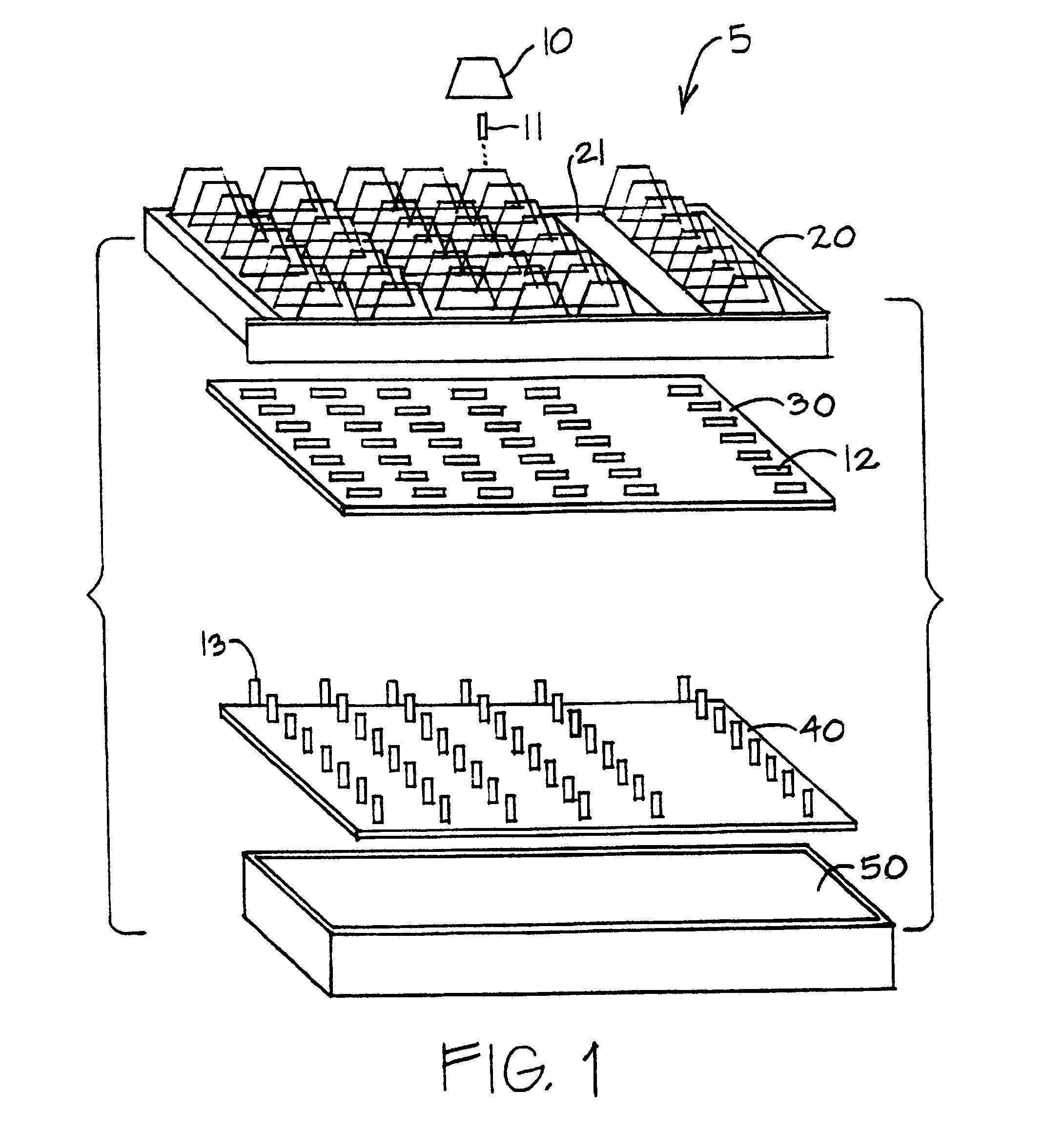
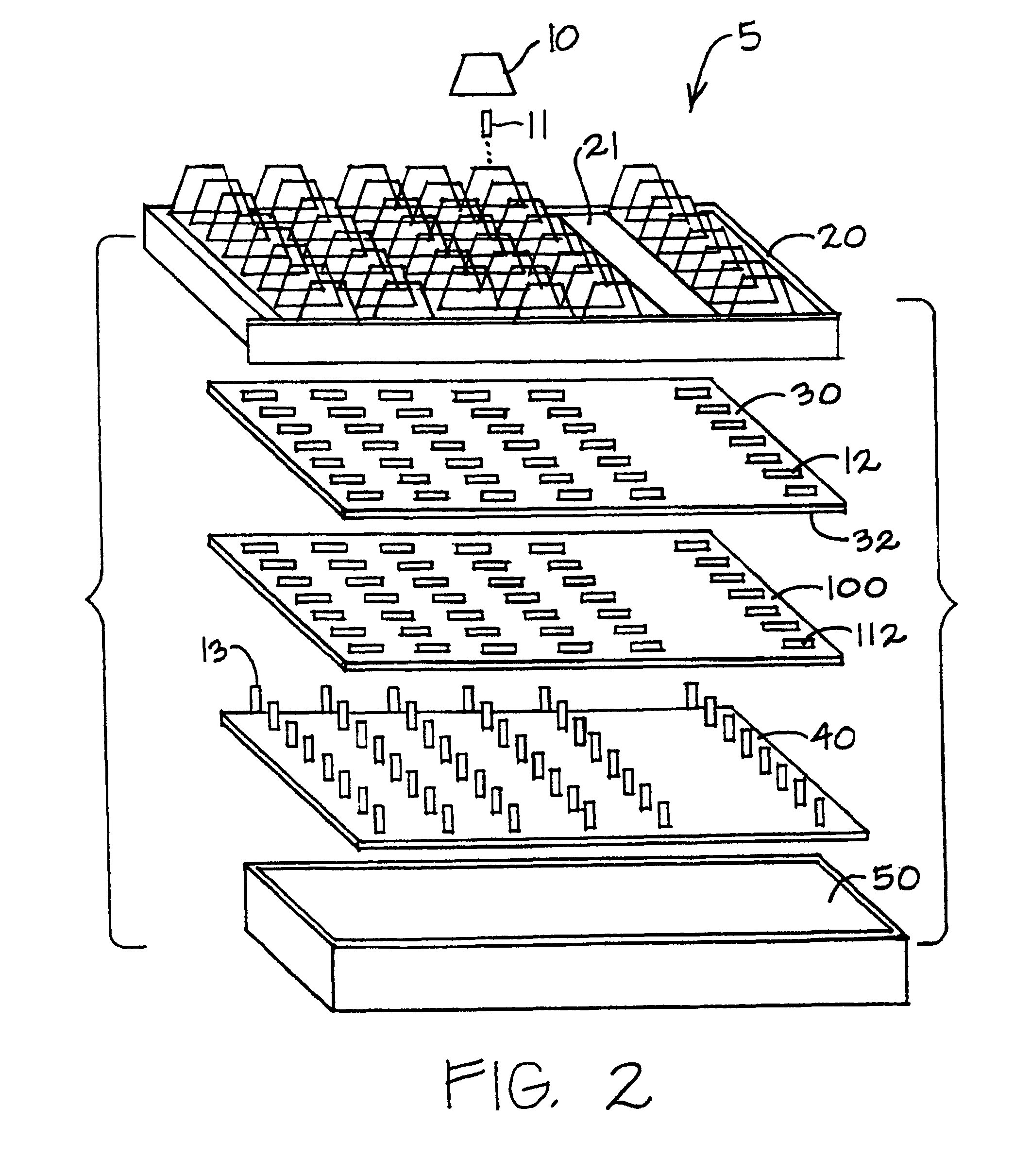
[0017]A functional diagram of the construction of a typical keyboard is shown in FIG. 1. Typically, a keyboard 5 is comprised of keypads 10, keystems 11, a keyboard top plate 20, a keyboard well plate 30, a circuit board 40 with key spring switches 13 and a key board bottom plate 50. Typically all of these components are manufactured of opaque materials. Keystems 11 are inserted through holes 12 in keyboard well plate 30. Holes 12 in keyboard well plate 30 are aligned with key spring switches 13 of circuit board 40. Circuit board 40 is secured to key board bottom plate 50. Key board top plate 20 fits over or otherwise attaches to key board bottom plate 50, and thereby provides enclosure for the keyboard. Typically, keys are grouped in a keyboard according to function. For example, on a typical keyboard for typing words and data into a word processor, a set of alphabet keys, number keys, and other certain symbol keys are grouped together in a traditional typewriter key layout, herein...


PUM


Abstract

Methods are provided for adapting existing manufacturing processes for non-illuminated data-entry devices and mouses to the manufacture of illuminated data-entry devices. Luminescent sheets of one or more colors underlying optically transmissive device components provide illumination of the components visual to a user of the device. The optically transmissive components may be doped with phosphors or tinted to provide components that emit light of different colors. The intensity of illumination of the luminescent sheet may be controlled by the user and may vary in response to the background light of the environment.

Description

[0001]This application is a divisional application and claims priority from co-pending U.S. patent application Ser. No. 10 / 867,272 filed on Jun. 14, 2004 now U.S. Pat. No. 7,284,872, which is a divisional application of U.S. patent application Ser. No. 09 / 755,775 file on Jan. 4, 2001 (now U.S. Pat. No. 6,773,128), which is a divisional application of U.S. patent application Ser. No. 09 / 139,927 filed on Aug. 26, 1998 (now U.S. Pat. No. 6,199,996), which are incorporated herein by reference.Technical Field of the Invention[0002]The present invention relates to illumination of keyboards, keypads, and other data entry devices.BACKGROUND OF THE INVENTION[0003]Keyboards, keypads, mouses, and other data entry devices (hereinafter referred to generally as keyboards) are used in a variety of applications for entry of alphanumeric and other types of data into a machine such as a calculator or computer. Keyboards have been developed that are light weight, low in cost, and relatively easy to ma...

Claims


Application Information

Patent Timeline
IPC IPC(8): F21V33/00H01H13/70
CPCH01H13/70H01H2219/018H01H2219/034H01H2219/038H01H2219/052
Inventor KATRINECZ, ANDREWBYRD, DAVID
Owner GOOGLE LLC
Why Eureka
Try Eureka