Wind turbine rotor blade and method of manufacturing such rotor blade

a technology of wind turbines and blades, which is applied in the direction of wind motor components, non-positive displacement fluid engines, liquid fuel engine components, etc., can solve the problems of blade surface shells being ripped apart, composite material delamination or incineration, heating and melting of metallic components,

Active Publication Date: 2011-02-08
VESTAS WIND SYST AS
View PDF6 Cites 34 Cited by
  • Summary
  • Abstract
  • Description
  • Claims
  • Application Information

AI Technical Summary

Benefits of technology

[0007]It may be seen as an object of the present invention to provide a wind turbine rotor blade having incorporated electrical conductivity means and still being able to divert strokes of lightning without the electrical conductivity means and / or the tip of the blade being damaged by the stroke of lightning.

Problems solved by technology

Problems are observed by strokes of lightning striking wind turbine rotor blade tips.
Common to the solutions is the risk of de-lamination or incineration of the surface composite material and / or heating and melting of metallic components.
There is also the risk that shock waves, caused by internal arcs, may explode the blades, ripping the blade surface shells apart along the edges and from the internal carrying spar.

Method used


Image

  • Wind turbine rotor blade and method of manufacturing such rotor blade
  • Wind turbine rotor blade and method of manufacturing such rotor blade
  • Wind turbine rotor blade and method of manufacturing such rotor blade

Examples


Embodiment Construction

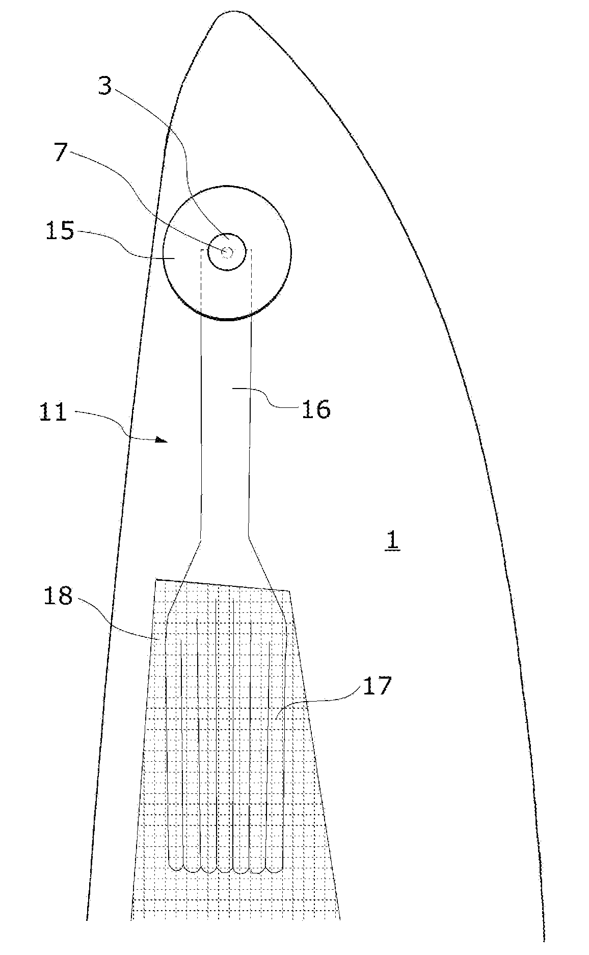
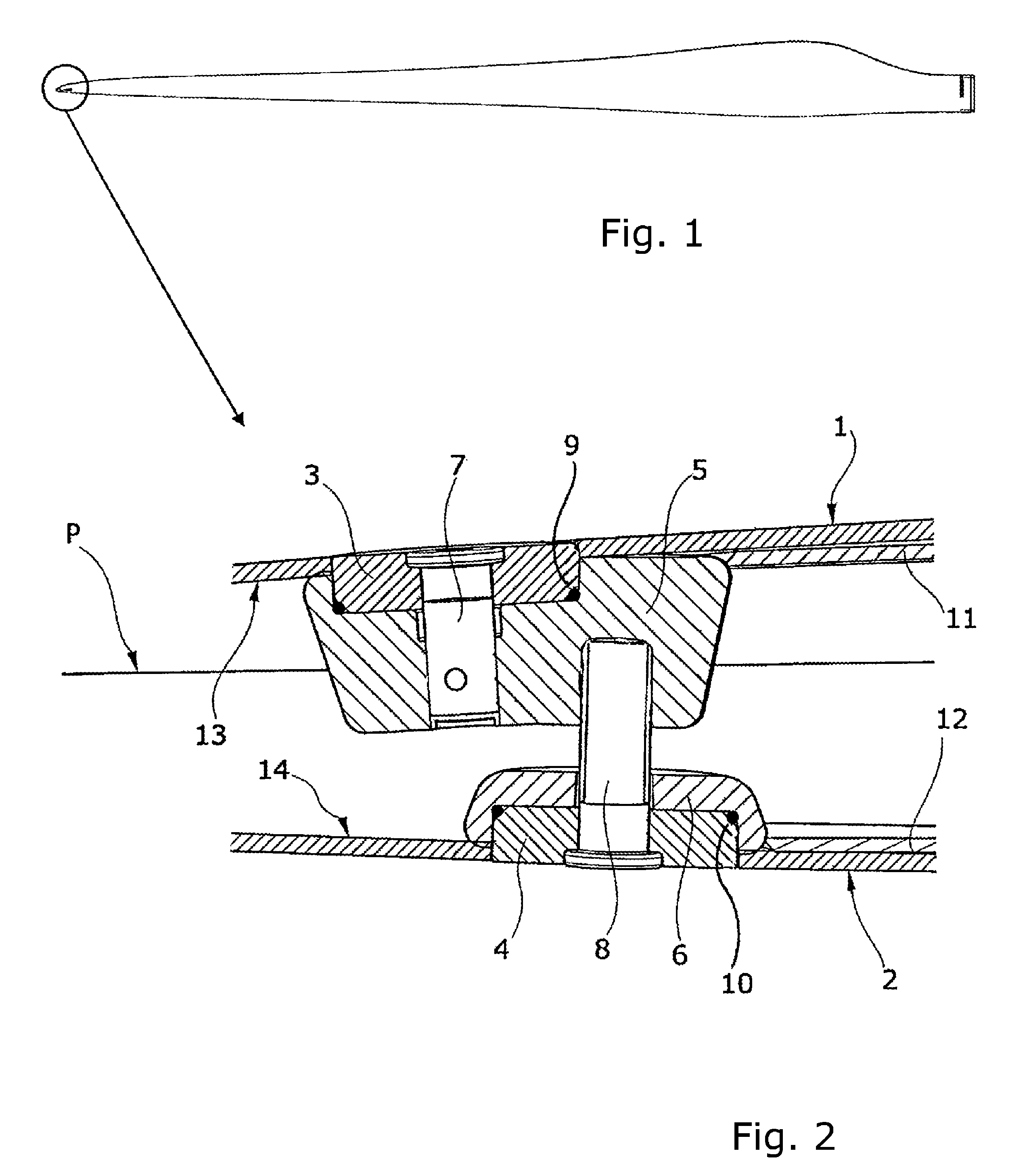
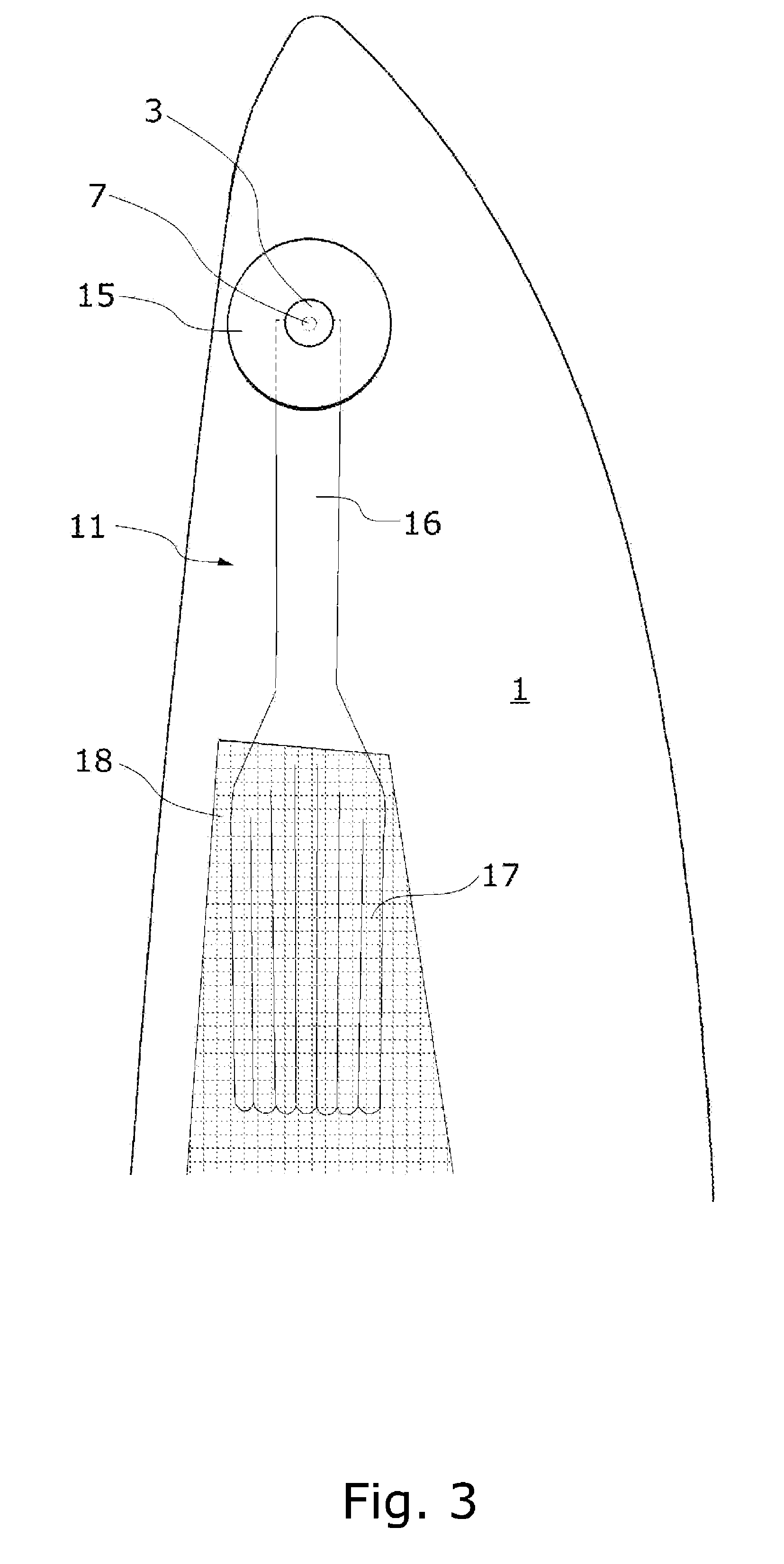
[0059]FIG. 1 is a plane view of a wind turbine rotor blade amongst other features also being provided in the tip of the blade with a lightning protection system as shown and described with reference to FIGS. 3-4. The blade may have a substantial length, i.e. a length of up to 50 m or even more. Blades having such magnitude may be manufactured by using manufacturing techniques that are alternative to the ones commonly used, e.g. by using wood, carbon fibres or other lightweight elements for obtaining a proper rigidity and strength together with the relative heavyweight resin also constituting part of the blade. Traditional manufacturing methods may also be employed for manufacturing the blade

[0060]FIG. 2 is a cross-section of a section of the tip of the wind turbine rotor blade, the cross-section being along a plane extending substantially transversely to and parallel with a rotor plane P of the blade. The rotor plane P of the blade is the plane in which the blade performs rotation, ...


PUM


Abstract

The invention relates to a wind turbine rotor blade comprising a blade tip and a lightning protection system. The blade includes at least one metallic lightning receptor at the surface of the blade in proximity of the distal end of the blade tip. The blade comprises a blade shell configured partly by a fibre-reinforced laminate, and the blade also comprises an electrically down-conducting element in the form of a metallic mesh. The electrically down-conducting element extends only to a certain distance from the distal end of the tip of the blade, said distance being larger than a distance between the position of the lightning receptor and the distal end of the tip of the blade. It is hereby ensured that a stroke of lightning will strike the receptor more likely than the electrically down-conducting element.

Description

PRIORITY CLAIM[0001]This is a U.S. national stage of application No. PCT / DK2008 / 050042, filed on Feb. 19, 2008. Priority is claimed on the following application: Country: Denmark, Application No.: PA200700258, Filed: Feb. 19, 2007, the content of which is incorporated here by reference.FIELD OF THE INVENTION[0002]The invention relates to a wind turbine rotor blade comprising a blade tip and a lightning protection system, said blade including at least one metallic lightning receptor at the surface of the blade in proximity of the distal end of the blade tip, and said blade possibly including a lightning receptor base within the surface of the blade, and said blade comprising a blade shell configured partly by a fibre-reinforced laminate, said blade comprising an electrically down-conducting element in the form of a metallic mesh.[0003]The invention also relates to a method of manufacturing a wind turbine rotor blade with a system for lightning protection of the tip of the blade, the ...

Claims


Application Information

Patent Timeline
Patent Type & Authority Patents(United States)
IPC IPC(8): F03D11/00
CPCF03D11/0033Y02E10/722Y02E10/721F03D80/30Y02E10/72Y02P70/50
Inventor BERTELSEN, KIM
Owner VESTAS WIND SYST AS
Why Eureka
Try Eureka