Power supply apparatus with fuel cell and method of controlling the same

a technology of power supply apparatus and fuel cell, which is applied in the direction of fuel cell water management, dc network circuit arrangement, electrochemical generators, etc., can solve the problems of difficult to directly apply a control practice of pefc to dmfc, limited range of use of fuel cells, and increasing the total power consumption of portable devices in the future. , to achieve the effect of stable power supply to equipment (loads) and stable operation of fuel cell units

Inactive Publication Date: 2011-02-08
HITACHI LTD
View PDF13 Cites 113 Cited by
  • Summary
  • Abstract
  • Description
  • Claims
  • Application Information

AI Technical Summary

Benefits of technology

[0013]According to the present invention, it is possible to provide a power supply apparatus and a method of controlling thereof for realizing the stable power supply to equipment (loads) and the stable operation of a fuel cell unit.

Problems solved by technology

However, it is expected that the total power consumption of a portable device will tend to increase in the future, because new functions should be added to provide improved services to meet user needs.
Therefore, a range of use of fuel cells must be limited up to the maximum power point.
It is difficult to directly apply a control practice for PEFC to DMFC, and a control practice specialized for DMFC is required.
Moreover, the DMFC output power may rapidly decrease for some cause (such as clogging of reaction by-products such as carbon dioxide or water).
However, it is supposed that the DMFC may become unable to supply required power according to the condition of the fuel cell as described above.
Drawing excessive current, if occurs, causes problematic conditions such as fuel cell deterioration by polarity inversion, fuel cell temperature rise, and deteriorating performance due to by-products such as carbon dioxide or water.
However, this poses problems in which state prediction of a high-speed fuel cell is very difficult and provision of a great number of sensors for prediction is costly.

Method used


Image

  • Power supply apparatus with fuel cell and method of controlling the same
  • Power supply apparatus with fuel cell and method of controlling the same
  • Power supply apparatus with fuel cell and method of controlling the same

Examples


first embodiment

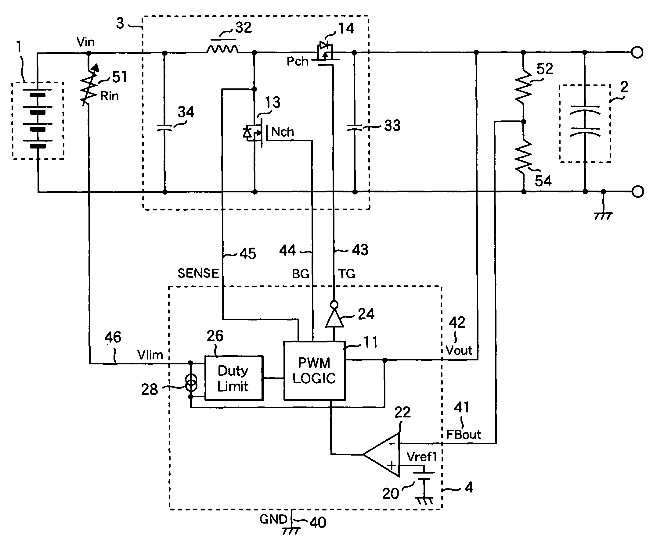
[0032]A first embodiment of the present invention is described, using FIG. 5.

[0033]A power supply apparatus of the present invention is broadly comprised of a fuel cell unit 1, an electric double layer capacitor (hereinafter referred to as a EDLC) 2 which is a charge storing device, a circuit section 3, and a control IC 4. Details of each constituent part will be described below.

[0034]In the present invention, the EDLC 2 used as the charge storing device has a withstand voltage of 2.3 V to 3.3 V per cell. If it is composed of two cells as shown in FIG. 5, it is applicable to equipment which has been conventionally driven by a single lithium battery cell or two nickel-metal-hydride (NiMH) cells. Such equipment is, for example, mobile phones, PDAs, digital still cameras, multimedia players, etc. In the case of applications where multiple lithium battery cells are used (e.g., notebook personal computers and the like), the EDLC 2 composed of two to four cells is compatible with two lith...

second embodiment

[0046]A second embodiment of the present invention is described, using FIG. 11. Unless specifically mentioned, components assigned the same reference numbers as in the foregoing circuit examples of the apparatus have the same structures and effects.

[0047]The power supply apparatus of the second embodiment has a configuration in which a fuel cell temperature control terminal is provided separately from the fuel cell voltage limitation terminal. As compared with the forging first embodiment, in the second embodiment apparatus, the fuel cell temperature control terminal (hereinafter referred to as TEMP) 48 is added to the control IC 4. Temperature information for the fuel cell unit 1 is obtained by a sensor 60 such as a thermistor or temperature IC, and input to the TEMP 48. The internal structure of the control IC 4 differs from the foregoing embodiment. Two feedback values, namely the Vout-Vlin value and the temperature voltage-Vref2 (29) value are input to the Duty Limit circuit 26....

third embodiment

[0049]A third embodiment of the present invention is described, using FIG. 12. Unless specifically mentioned, components assigned the same reference numbers as in the foregoing circuit examples of the apparatus have the same structures and effects.

[0050]As compared with the first and second embodiments, the third embodiment is an example of a power supply apparatus in which the circuit portion 3 is not the synchronous rectification type and has changed to a step-up chopper type employing a schottky diode 35. This configuration is effective for increasing the voltage at the output end of the apparatus, higher than the apparatuses of the first and second embodiments.

[0051]Detail of the control IC 4 will be described below. As compared with the first and second embodiments, the control IC 4 of the third embodiment dispenses with the P-channel power MOSFET control terminal (TG). For the internal structure of the control IC 4, either the corresponding structure in the first embodiment ap...


PUM

PropertyMeasurementUnit
voltageaaaaaaaaaa
constant set voltageaaaaaaaaaa
voltageaaaaaaaaaa

Abstract

A power supply apparatus has a fuel cell unit as a source of input power. A control device limits the output of the fuel cell unit within an operating range of up to a maximum power point, even if a load power is not lower than the maximum power of said fuel cell unit. In addition to the fuel cell, a charge storing device is provided at the output side of the power supply apparatus. The charge storing device is capable of making up a shortage of power of the fuel cell.

Description

CLAIM OF PRIORITY[0001]The present application claims priority from Japanese application serial no. 2005-286436, filed on Sep. 30, 2005, the content of which is hereby incorporated by reference into this application.FIELD OF THE INVENTION[0002]The present invention relates to a power supply apparatus using a fuel cell and a method of controlling the same apparatus.BACKGROUND OF THE INVENTION[0003]With recent advances of electronic technologies, there is an accelerating proliferation of portable electronic equipment such as mobile phones, notebook personal computers, audio / visual devices, and mobile terminal devices. The portable electronic equipment is usable by a secondary battery. New types of secondary batteries have been introduced. With the aim of developing smaller and lighter batteries and those with a higher energy density, the secondary batteries have been evolved from sealed lead batteries to nickel-cadmium cells, nickel-hydrogen cells, and lithium ion cells. For any type ...

Claims


Application Information

Patent Timeline
Patent Type & Authority Patents(United States)
IPC IPC(8): H01M8/04
CPCH01M8/04007H01M8/04365H01M8/04559H01M8/04567H01M8/04597H01M8/04619H01M8/04626H01M8/0488H01M8/04888H01M8/0494H01M8/04947H01M8/1011H01M16/006H02J7/34H01M8/04291H02J2001/004Y02E60/523H02J2300/30Y02E60/10Y02E60/50
Inventor NORIMATSU, YASUAKIKANOUDA, AKIHIKOKIKUCHI, MUTSUMI
Owner HITACHI LTD
Why Eureka
Try Eureka