
Air conditioning system

a technology of air conditioning system and air conditioner, which is applied in the field of air conditioning system, can solve the problems of reducing the coefficient of performance (cop), not achieving sensible heat load, increasing the number of parts to be maintained, and increasing the cost and cos

Inactive Publication Date: 2011-02-15
DAIKIN IND LTD
View PDF19 Cites 3 Cited by
  • Summary
  • Abstract
  • Description
  • Claims
  • Application Information

AI Technical Summary

Benefits of technology

This configuration reduces power consumption, improves the coefficient of performance (COP), and minimizes the number of components and maintenance requirements by integrating heat sources and allowing for flexible operation between dehumidification and humidification based on room needs.

Problems solved by technology

Consequently, the difference between high and low pressures in the vapor compression refrigeration cycle increases and so does the power consumption of the compressor, resulting in a reduced coefficient of performance (COP).
Therefore, this dehumidifier can treat the latent heat load in the room but not the sensible heat load, which has been a problem.
However, in some cases, in such a large scale air conditioning system, a plurality of air conditioners each comprising an adsorbent heat exchanger are needed, so that several compressors and the like to be used as heat sources may need to be installed according to the number of the adsorbent heat exchangers, which consequently creates problems such as an increase in cost and an increase in the number of parts to be maintained.
In addition, when the air conditioner comprising the adsorbent heat exchanger is installed along with an air conditioner comprising a typical air heat exchanger, a compressor and the like to be used as heat sources must be installed separately from the air conditioner comprising the air heat exchanger, which consequently creates problems such as an increase in cost and an increase in the number of parts to be maintained.

Method used


Image

  • Air conditioning system
  • Air conditioning system
  • Air conditioning system

Examples


first embodiment

(1) Configuration of the Air Conditioning System

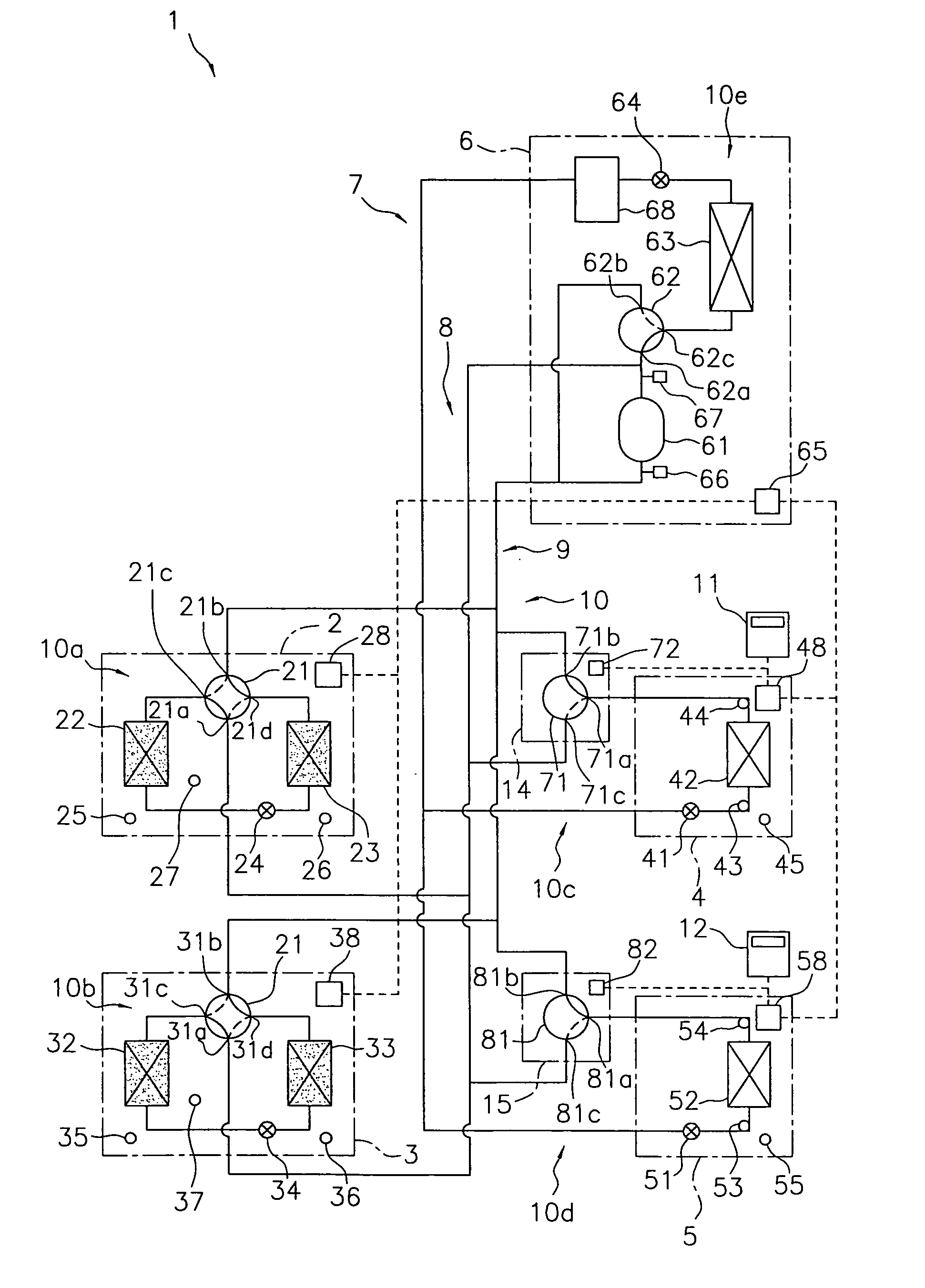
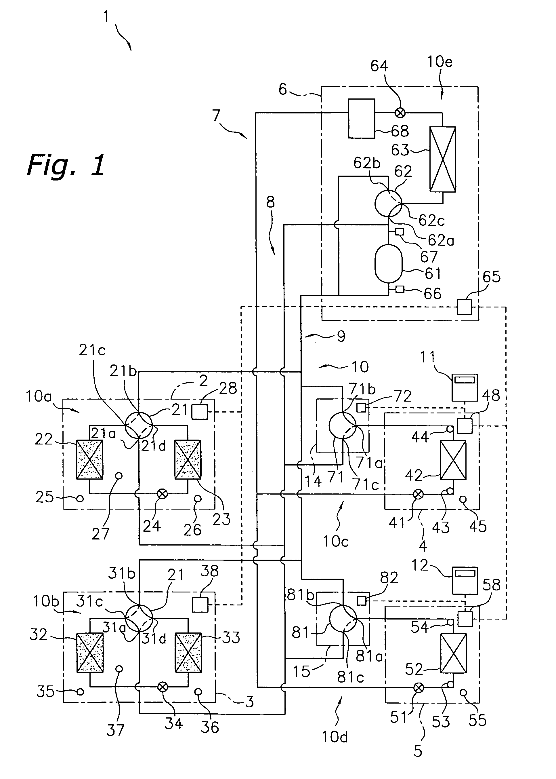
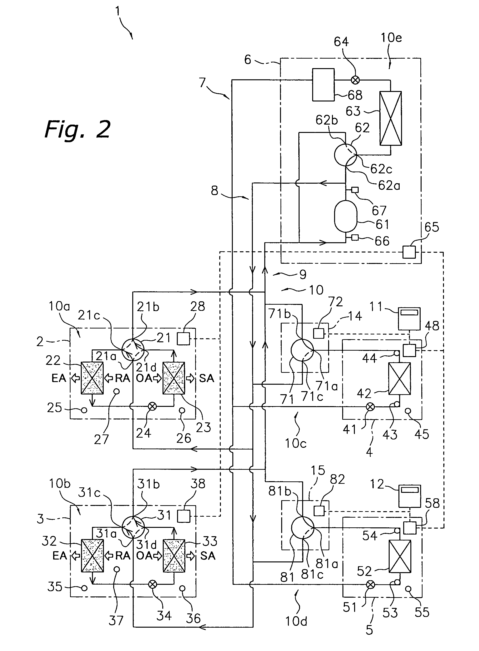
[0128]FIG. 1 a schematic diagram of a refrigerant circuit of an air conditioning system 1 of a first embodiment according to the present invention. The air conditioning system 1 is an air conditioning system that treats the latent heat load and the sensible heat load in the room of a building and the like by operating a vapor compression type refrigeration cycle. The air conditioning system 1 is so-called separate type multi air conditioning system, and mainly comprises: a plurality (two in this embodiment) of latent heat utilization units 2, 3 connected in parallel with one another; a plurality (two in this embodiment) of sensible heat utilization units 4, 5 connected in parallel with one another; a heat source unit 6; and connection pipes 7, 8, 9 which connect the latent heat utilization units 2, 3 and the sensible heat utilization units 4, 5 to the heat source unit 6. In the present embodiment, the heat source unit 6 functions as a ...

second embodiment

[0317]In the air conditioning system 1 of the above-described first embodiment, the sensible heat utilization side refrigerant circuits 10c, 10d are connected to the liquid connection pipe 7 that is connected to the liquid side of the heat source side heat exchanger 63 of the heat source side refrigerant circuit 10e, and also are switchably connected between the discharge gas connection pipe 8 and the inlet gas connection pipe 9 through the air conditioning switching valves 71, 81, and thereby, in each of the sensible heat utilization side refrigerant circuits 10c, 10d, the air heat exchangers 42, 52 can be caused to function as evaporators or condensers. As a result, an air conditioning system capable of so-called simultaneous cooling and heating operations is achieved, in which cooling and heating are simultaneously performed depending on the needs of each air-conditioned room, for example, cooling an air-conditioned room while heating a different air-conditioned room. However, as...

third embodiment

(1) Configuration of the Air Conditioning System

[0324]FIG. 36 a schematic diagram of a refrigerant circuit of an air conditioning system 401 of a third embodiment according to the present invention. The air conditioning system 401 is an air conditioning system that treats the latent heat load and the sensible heat load in the room of a building and the like by operating a vapor compression type refrigeration cycle. The air conditioning system 401 is a separate type multi air conditioning system, and mainly comprises a plurality (two in this embodiment) of latent heat utilization units 2, 3 connected in parallel with one another, a plurality (two in this embodiment) of sensible heat utilization units 404, 405 connected in parallel with one another, a heat source unit 406, and connection pipes 407, 408, 409 which connect the latent heat utilization units 2, 3 and the sensible heat utilization units 404, 405 to the heat source unit 406. In the present embodiment, the heat source unit 4...


PUM


Abstract

An air conditioning system includes a plurality of latent heat utilization side refrigerant circuits which are connected in parallel with one another, and a plurality of sensible heat utilization side refrigerant circuits which are connected in parallel with one another. The latent heat utilization side refrigerant circuits include adsorbent heat exchangers provided with an adsorbent on the surface of each. The sensible heat utilization side refrigerant circuits respectively include air heat exchangers and are capable of exchanging heat between the refrigerant and air.

Description

CROSS-REFERENCE TO RELATED APPLICATIONS[0001]This U.S. National stage application claims priority under 35 U.S.C. §119(a) to Japanese Patent Application No. 2004-105173, filed in Japan on Mar. 31, 2004, the entire contents of which are hereby incorporated herein by reference.TECHNICAL FIELD[0002]The present invention relates to an air conditioning system. More specifically, the present invention relates to an air conditioning system in which the latent heat load and the sensible heat load in the room are treated by operating a vapor compression refrigeration cycle.BACKGROUND ART[0003]Conventionally, air conditioners that cool and dehumidify the room are known (for example, see International Publication WO 03 / 029728). This type of air conditioner comprises a vapor compression refrigerant circuit having an outdoor heat exchanger as a heat source side heat exchanger and an indoor heat exchanger as an air heat exchanger, and a refrigerant is circulated in this refrigerant circuit to ope...

Claims


Application Information

Patent Timeline
Patent Type & Authority Patents(United States)
IPC IPC(8): F25D23/00F24F3/14F24F5/00F24F11/02F25B13/00
CPCF24F3/1411F25B13/00F24F3/1429F25B2313/0233F25B2313/0311F25B2313/0314F24F11/61
Inventor FUJIYOSHI, RYUSUKEYABU, TOMOHIRO
Owner DAIKIN IND LTD
Learn More