
Partial air inlet control strategy for air conditioning system

a technology of air conditioning system and control strategy, which is applied in the direction of vehicle cleaning, vessel parts, vessel construction, etc., can solve the problems of reducing affecting the efficiency of heating/cooling, and the optimization of parameters, so as to achieve the effect of increasing noise, vibration and harshness

Active Publication Date: 2020-05-05
FORD GLOBAL TECH LLC
View PDF32 Cites 0 Cited by
  • Summary
  • Abstract
  • Description
  • Claims
  • Application Information

AI Technical Summary

Benefits of technology

The invention provides a way to optimize the air intake between 100% fresh air and 100% recirculated air in vehicles, which improves fuel economy and reduces battery power consumption without compromising passenger comfort. This is achieved by selectively choosing a position between the two modes, reducing the load on the compressor and improving air conditioning performance in cooling applications. The invention also enhances heating performance in IC vehicles, reduces engine on time in HEVs, and reduces HV battery power consumption in EVs. Overall, the invention improves the performance of vehicles in terms of fuel economy, battery power consumption, and overall driving experience.

Problems solved by technology

However, for all types of vehicles there is a trade-off between these parameters.
Particularly, for the internal combustion (IC) vehicle (including the hybrid electric vehicle [HEV]), fuel economy will suffer to maximize heating / cooling performance.
If the management of the air entering the HVAC is not managed carefully these parameters may not be optimized.
On the other hand, if the fresh air mode is selected as the source of air for the HVAC system in cold weather, this air mode will slow down heater / defrost performance.
Yet when the recirculation mode is selected to provide 100% of the incoming air for the HVAC, a potential result, in certain ambient conditions, is cabin fogging.

Method used


Image

  • Partial air inlet control strategy for air conditioning system
  • Partial air inlet control strategy for air conditioning system
  • Partial air inlet control strategy for air conditioning system

Examples


Embodiment Construction

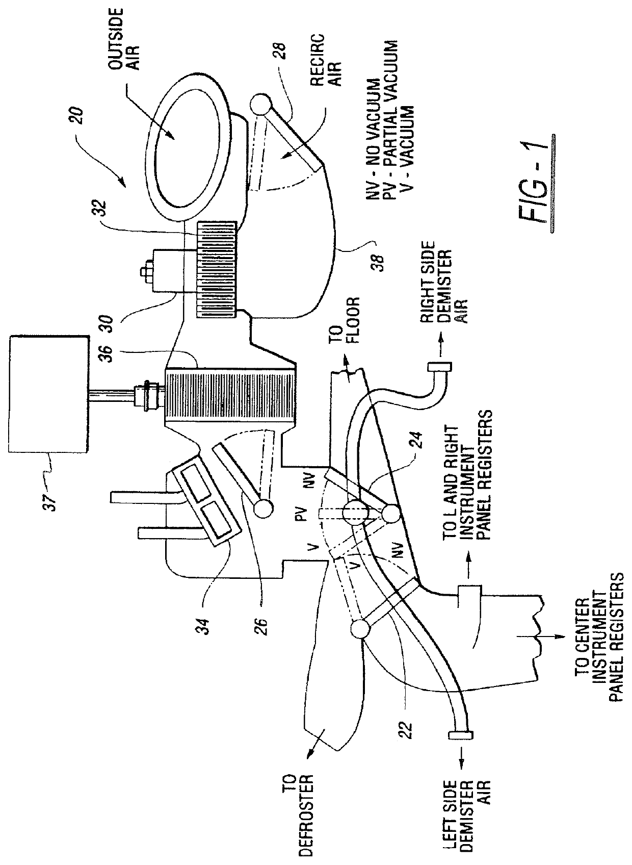
[0018]In the following figures, the same reference numerals will be used to refer to the same components. In the following description, various operating parameters and components are described for different constructed embodiments. These specific parameters and components are included as examples and are not meant to be limiting. In general, control of air temperature and air flow (and to a lesser extent, humidity) within an automobile is achieved using various actuators to affect the temperature and flow of air supplied to the cabin of the vehicle. FIG. 1 shows schematically an air handling system of a heating, ventilation and air conditioning (HVAC) system, generally indicated as 20. The system 20 includes an arrangement of a panel-defrost door 22, a floor-panel door 24, a temperature blend door 26 and outside recirculation air door 28. It is to be understood that the door 28 functions to regulate air passage between fresh air and recirculated air. Any of a variety of air flow re...


PUM


Abstract

A system and method of selecting air intake between 100% fresh air mode and 100% recirculated air mode for optimum heating / cooling performance, fuel economy and / or high voltage (HV) battery power consumption is disclosed. The system and method includes a partial recirculation control strategy in which the air inlet door is moved progressively to any position by taking into account cooling / heating loads and cabin fogging probability. As cooling / heating loads increase the air inlet door moves toward 100% recirculation mode. As fogging probability increases the air inlet door moves toward 100% fresh air mode. By selectively choosing a position between 100% recirculation and 100% fresh air, fuel economy and / or HV battery power consumption is optimized without compromising passenger comfort or causing fogging on interior glass surfaces. In cooling applications the compressor load is minimized and air conditioning performance is improved due to the reduced evaporator cooling load. The direct result of this improvement is increased fuel economy in the case of the internal combustion vehicle, reduced engine on time in the case of the hybrid electric vehicle (due to reduced HV battery power consumption), and reduced HV battery power consumption in the case of the hybrid electric vehicle (HEV) and the electric vehicle (EV). In heating applications, as the heating load is reduced the fuel economy of the internal combustion (IC) engine will be improved, the engine on time is reduced in the case of the HEV, and HV battery power consumption is reduced in the case of the EV.

Description

TECHNICAL FIELD[0001]The disclosed invention relates generally to a system for regulating incoming air flow in a vehicle heating / cooling system. More particularly, the disclosed invention relates to a system and method for providing an efficient selection between 100% fresh air mode and 100% recirculated air mode to optimize heating / cooling performance while increasing fuel economy in the case of the internal combustion (IC) vehicle, increasing engine off time in the case of the hybrid vehicle, and reducing high voltage (HV) battery power consumption in the case of the electric vehicle.BACKGROUND OF THE INVENTION[0002]Improved fuel economy for the internal combustion engine-powered vehicle has long been a goal of automobile manufacturers. With the advent of the hybrid electric vehicle (HEV) a new goal, reducing engine on time, has been created. With the electric vehicle (EV) the goal is to minimize power consumption from the high voltage (HV) battery. Challenging achievement of thes...

Claims


Application Information

Patent Timeline
Patent Type & Authority Patents(United States)
IPC IPC(8): B60H1/00
CPCB60H1/00849B60H1/00764B60H1/00785
Inventor WIJAYA, HALIMMADHAVAN, RANGANATHANJONES, CURTIS M.KOBERSTEIN, MANFRED
Owner FORD GLOBAL TECH LLC
Learn More