Exhaust gas reflux mechanism for multipurpose engine

a multi-purpose, exhaust gas technology, applied in the direction of machines/engines, mechanical equipment, output power, etc., can solve the problems of increasing reducing the efficiency of the engine, and large the size of the reflux apparatus, so as to reduce the concentration of nox in the exhaust gas, reduce the overall size and weight of the engine, and simple construction

Inactive Publication Date: 2011-02-15
HONDA MOTOR CO LTD
View PDF15 Cites 1 Cited by
  • Summary
  • Abstract
  • Description
  • Claims
  • Application Information

AI Technical Summary

Benefits of technology

[0009]After a start-up of the multipurpose engine, the engine speed automatically increases up to a predetermined operating speed (i.e., a rated speed). While the intake valve stays open during the intake stroke of the engine, the exhaust valve is opened by the action of the cam lobe of the exhaust reflux cam. As a result, part of an exhaust gas remaining on the side of an exhaust port of the engine is sucked or drawn into a combustion chamber of the engine during the intake stroke. Thus, from the start-up of the engine, a reflux of exhaust gas occurs during the intake stroke of the engine. During combustion of an air-fuel mixture during an expansion stroke in a later stage, the refluxed exhaust gas inhibits an excessive increase in combustion temperature of the air-fuel mixture, to reduce NOx concentration in the exhaust gas.
[0010]Since the exhaust gas reflux mechanism is comprised of an exhaust reflux cam which is formed integrally with the single cam of the multipurpose engine as an integral part of the single cam, the exhaust gas reflux mechanism is simple in construction and small in size and weight, which will lead to downsizing and cost-reduction of the multipurpose engine.
[0013]Preferably, the cam lobe of the exhaust reflux cam is profiled to finish closing of the exhaust valve at the end of the intake stroke. This arrangement is advantageous for highly efficient reduction of NOx concentration in the exhaust gas.

Problems solved by technology

Furthermore, due to the use of the auxiliary rocker arm, the shift fork and the actuator, the conventional exhaust gas reflux apparatus is relatively large in size and complicated in construction, which will increase the overall size and weight of the engine.

Method used


Image

  • Exhaust gas reflux mechanism for multipurpose engine
  • Exhaust gas reflux mechanism for multipurpose engine
  • Exhaust gas reflux mechanism for multipurpose engine

Examples


Embodiment Construction

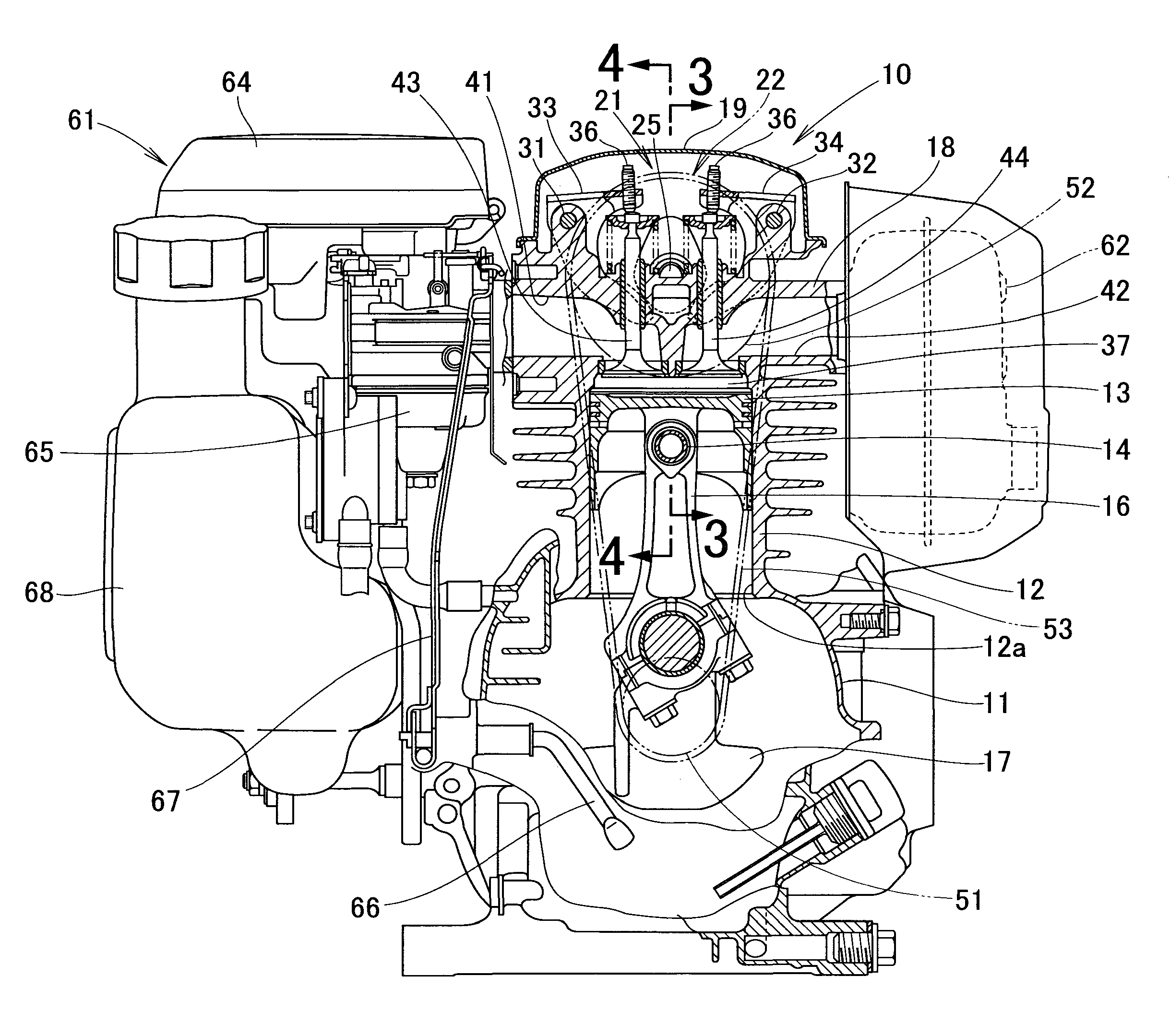
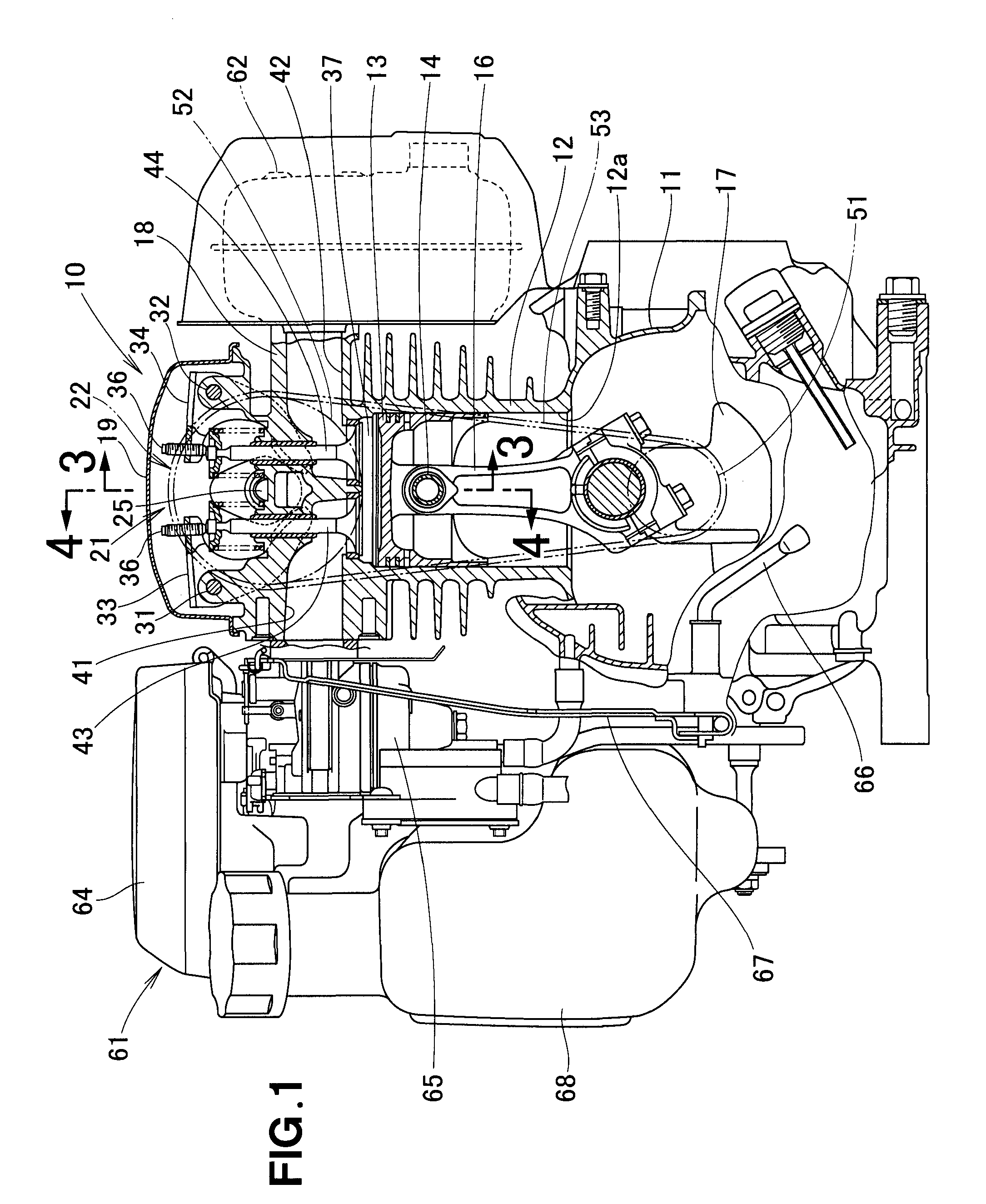
[0023]Referring now to the drawings and FIG. 1 in particular, there is shown a multipurpose engine 10 in which an exhaust gas reflux mechanism embodying the present invention is incorporated. The engine to includes a crankcase 11, a cylinder block 12 mounted to an upper end of the crankcase 11, a piston 13 slidably received in a cylinder bore 12a formed in the cylinder block 12, a connecting rod 16 pivotally connected at one end to the piston 13 by a piston pin 14, a crankshaft 17 connected to the other end of the connecting rod 16 and rotatably supported by mating surfaces of the crankcase 11 and the cylinder block12, a cylinder head 18 formed integrally with an upper part of the cylinder block 12, a head cover 19 that closes an upper opening of the cylinder head 18, a valve operating mechanism 21 provided on the cylinder head 18, a timing drive mechanism 22 for driving the valve operating mechanism 21 in timed relation to rotation of the crankshaft 17, and a governor (not shown) f...


PUM


Abstract

An exhaust gas reflux mechanism for a multipurpose engine includes an exhaust reflux cam formed as an integral part of an single cam of the engine and having a cam lobe profiled to open an exhaust valve while an intake valve stays open during the intake stroke of the engine so that part of an exhaust gas remaining on the side of an exhaust port of the engine is drawn into a combustion chamber during the intake stroke.

Description

FIELD OF THE INVENTION[0001]The present invention relates to an improvement in an exhaust gas reflux mechanism for a multipurpose engine.BACKGROUND OF THE INVENTION[0002]An example of conventional exhaust gas reflux apparatus is disclosed in Japanese Patent Laid-open Publication (JP-A) No. 2004-169687 (corresponding to U.S. Pat. No. 6,892,714). The disclosed exhaust gas reflux apparatus is configured such that a reflux of exhaust gas into a combustion chamber is controlled according to the opening degree of a throttle valve.[0003]More particularly, the exhaust gas reflux apparatus shown in JP 2004-169687A includes a pair of supports disposed on a cylinder head, an auxiliary rocker shaft supported by the supports, an auxiliary rocker arm placed between the supports and pivotably and axially slidably supported by the auxiliary rocker shaft, an interlock pin protruding from an intake rocker arm and axially slidably fitted in a slot formed in one end of the auxiliary rocker arm, a gap a...

Claims


Application Information

Patent Timeline
Patent Type & Authority Patents(United States)
IPC IPC(8): F02D13/00F01L1/34
CPCF01L1/053F01L1/181F01L13/0015F02M25/0752F01L2001/0535F01L2800/10Y02T10/121F02M26/01
Inventor KASHIMA, SOJI
Owner HONDA MOTOR CO LTD
Why Eureka
Try Eureka