Biomass charcoal gas co-production coupled biomass power generation system and biomass power generation method

A biomass power generation and biomass charcoal technology, which is applied in the direction of combustion methods, biofuels, gaseous fuel supply/distribution, etc., can solve the problems of low temperature corrosion, dust accumulation in the air preheater of biomass direct-fired boilers, etc., and achieve the purpose of slowing down the accumulation Ash and low-temperature corrosion, increase air temperature, slow down the effect of boiler ash and low-temperature corrosion

Pending Publication Date: 2021-05-28
大成华钰(北京)环境科技有限公司
View PDF0 Cites 0 Cited by
  • Summary
  • Abstract
  • Description
  • Claims
  • Application Information

AI Technical Summary

Problems solved by technology

[0003] The purpose of the present invention is to provide a biomass charcoal gas cogeneration coupling biomass power generation system and a biomass power generation method to solve the problems of dust accumulation and low-temperature corrosion in the air preheater of the biomass direct-fired boiler

Method used


Image

  • Biomass charcoal gas co-production coupled biomass power generation system and biomass power generation method

Examples


Embodiment 1

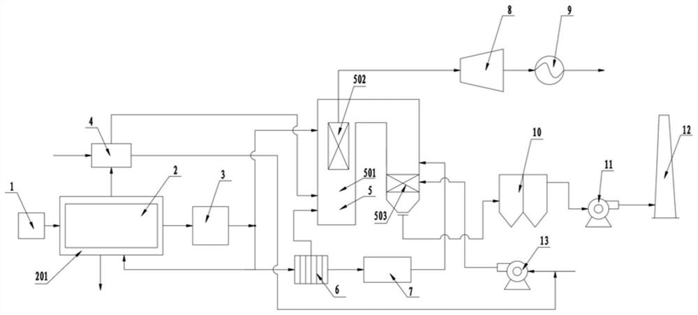
[0036] Such as figure 1 As shown, the biomass charcoal-gas cogeneration coupling biomass power generation system provided by the embodiment of the present invention includes: feeding equipment 1, charcoal-gas cogeneration equipment 2, gas purification equipment 3, heat exchanger 4, biomass direct-fired boiler 5. Gas purification equipment 6, pulse soot blowing equipment 7 and boiler blower 13;

[0037] The feeding device 1 is in communication with the charcoal-gas cogeneration device 2, the flue gas outlet of the charcoal-gas cogeneration device 2 is in fluid communication with the heat exchanger 4, and the gas outlet of the charcoal-gas cogeneration device 2 is in fluid communication with the gas purification device 3;

[0038] The flue gas outlet of the heat exchanger 4 is in fluid communication with the combustion chamber 501 of the biomass direct-fired boiler 5;

[0039] The air inlet of the boiler blower 13 is in fluid communication with the air outlet of the heat exchan...

Embodiment 2

[0056] Such as figure 1 As shown, the biomass power generation method provided in the embodiment of the present invention adopts the biomass charcoal gas cogeneration coupled biomass power generation system provided in Embodiment 1, and includes the following steps:

[0057] The biomass is sent to the charcoal-gas cogeneration equipment 2, and the biomass undergoes pyrolysis and carbonization reaction and is transformed into biochar and combustible gas, and the combustible gas is passed into the gas purification device 3 for purification;

[0058] The purified clean gas is passed into the heating chamber 201 of the charcoal-gas cogeneration equipment 2, the combustion chamber 501 of the biomass direct-fired boiler 5, and the gas purification equipment 6 respectively. The gas burns and releases heat in the heating chamber 201 of the charcoal-gas cogeneration equipment 2 and the combustion chamber 501 of the biomass direct-fired boiler 5; the gas is purified in the gas purificat...


PUM


Abstract

The invention provides a biomass charcoal gas co-production coupled biomass power generation system and a biomass power generation method, and relates to the technical field of biomass power generation. The system comprises a feeding device, a carbon-gas co-production device, a fuel gas purification device, a heat exchanger, a biomass direct-fired boiler, a fuel gas purification device, a pulse soot blower and a boiler blower. The feeding equipment is communicated with the carbon-gas co-production equipment, a flue gas outlet of the carbon-gas co-production equipment is in fluid communication with the heat exchanger, and a fuel gas outlet of the carbon-gas co-production equipment is in fluid communication with the fuel gas purification equipment; a fuel gas outlet of the fuel gas purification equipment is in fluid communication with the fuel gas purification equipment, a purified fuel gas outlet of the fuel gas purification equipment is in fluid communication with the pulse soot blower, and a gas outlet of the pulse soot blower is in fluid communication with the biomass direct-fired boiler. According to the biomass charcoal-gas co-production coupled biomass power generation system, the problems of ash deposition and low-temperature corrosion of the air pre-heater of the biomass direct-fired boiler can be solved.

Description

technical field [0001] The invention relates to the technical field of biomass power generation, in particular to a biomass charcoal gas cogeneration coupled biomass power generation system and a biomass power generation method. Background technique [0002] In the process of biomass direct combustion power generation, due to the high content of alkali metals in the biomass ash produced by biomass combustion, it is easy to cause dust accumulation and low-temperature corrosion in the air preheater of the flue flue at the bottom of the boiler. Especially during winter operation, due to the low temperature of the air entering the air pipe of the terminal air preheater, condensation is easily formed on the contact surface of the air preheater flue gas, which in turn causes biomass ash to stick to the outer wall of the air preheater. Aggravate the low temperature corrosion of the air preheater. Dust accumulation and low-temperature corrosion in the air preheater lead to continuo...

Claims


Application Information

Patent Timeline
Patent Type & Authority Applications(China)
IPC IPC(8): C10B53/02F23L5/00F23L15/00F23K5/00
CPCC10B53/02F23K5/002F23L5/00F23L15/00Y02E20/34Y02E50/10Y02P20/129
Inventor 李宏江王云红
Owner 大成华钰(北京)环境科技有限公司
Why Eureka
Try Eureka