Industrial pulverized coal boiler burning device used for spraying ammonia in center of burner

A pulverized coal boiler and combustion device technology, which is applied to burners, burners, combustion methods and other directions for burning powder fuels, can solve the problems of poor load change adjustment capability, high NOx emission reduction costs, and high NOx emissions, and achieves a reduction in Contact, the effect of reducing slagging in furnace and reducing NOx content

Active Publication Date: 2017-12-15
HARBIN INST OF TECH
View PDF7 Cites 10 Cited by
  • Summary
  • Abstract
  • Description
  • Claims
  • Application Information

AI Technical Summary

Problems solved by technology

[0005] In order to solve the problems of high NOx emission, high NOx emission reduction cost, poor pulverized coal burnout, poor adjustment ability to load changes, low boiler thermal efficiency and serious slagging existing in the existing horizontal industrial pulverized coal boiler, the present invention, Furthermore, a combustion device for injecting ammonia in the center of the burner for industrial pulverized coal boilers is proposed

Method used


Image

  • Industrial pulverized coal boiler burning device used for spraying ammonia in center of burner
  • Industrial pulverized coal boiler burning device used for spraying ammonia in center of burner

Examples


specific Embodiment approach 1

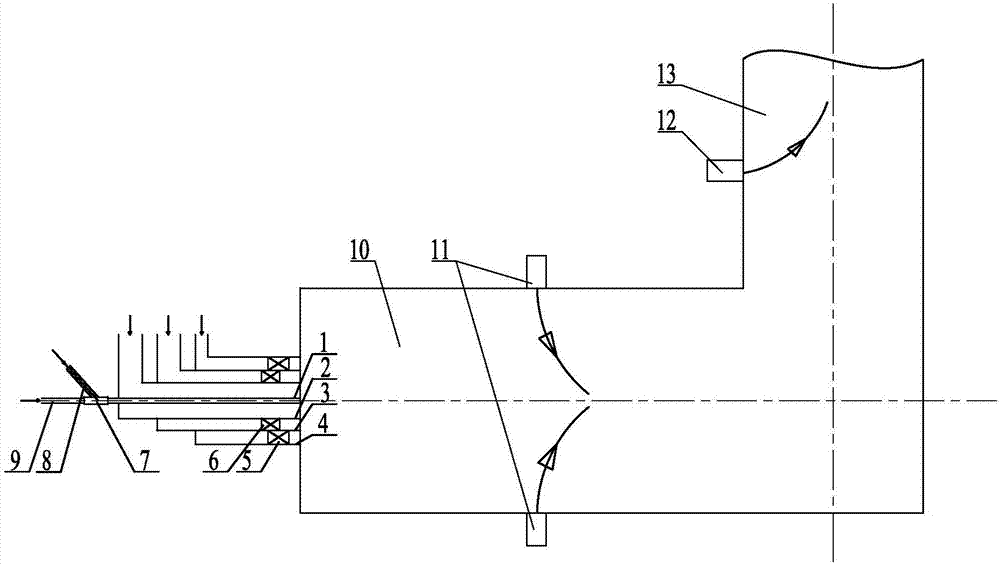
[0022] Specific implementation mode one: combine figure 1 and figure 2 Describe this embodiment, a combustion device for injecting ammonia in the center of the burner for an industrial pulverized coal boiler in this embodiment includes a primary air duct 1, a direct current secondary air duct 2, a secondary air duct 3 in a swirling flow, Secondary air pipe 4 outside the swirling flow, mixer 7, amino reducing agent conveying pipe 8, concentrated pulverized coal conveying pipe 9, furnace 10 and two-stage burn-off air system, primary air pipe 1, DC secondary air pipe 2, cyclone The secondary air pipe 3 inside the flow and the secondary air pipe 4 outside the swirling flow are arranged sequentially from the inside to the outside, the amino reducing agent delivery pipe 8 and the concentrated pulverized coal delivery pipe 9 are respectively connected to the inlet end of the mixer 7, and the outlet of the mixer 7 The outlet end is connected to the inlet end of primary air duct 1, a...

specific Embodiment approach 2

[0023] Specific implementation mode two: combination figure 1This embodiment is described. The primary air duct 1 , the DC secondary air duct 2 , the secondary air duct 3 inside the swirl flow, and the secondary air duct 4 outside the swirl flow described in this embodiment are arranged coaxially. The undisclosed technical features in this embodiment are the same as those in the first embodiment.

specific Embodiment approach 3

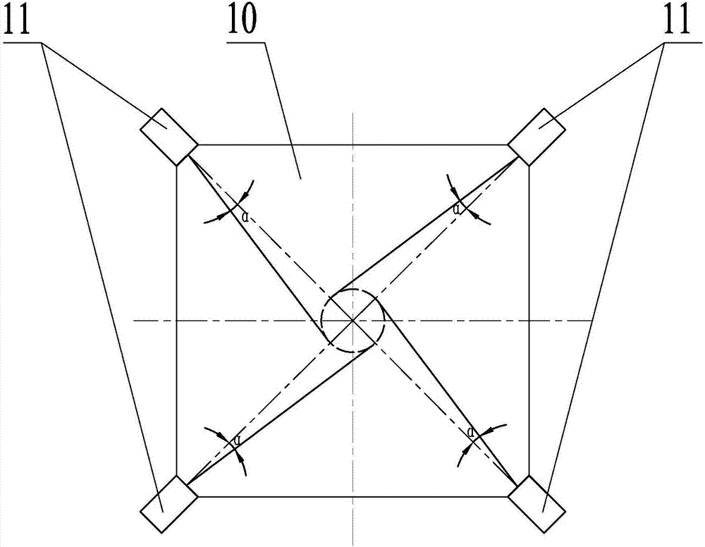
[0024] Specific implementation mode three: combination figure 1 and figure 2 Describe this embodiment. The two-stage overfire air system in this embodiment includes multiple primary overfire air nozzles 11 and multiple secondary overfire air nozzles 12. The vertical circumferential direction of each primary overburning air nozzle 11 is set at an angle α between the injection direction and the center of the furnace 10, and the secondary overburning air nozzle 12 is arranged on the upward flue 13 of the furnace 10 On the front wall, multiple secondary burn-off air nozzles 12 are evenly distributed along the horizontal circumferential direction of the upward flue 13 . The undisclosed technical features in this embodiment are the same as those in the first or second specific embodiment.

[0025] The injection direction of each primary overburning air spout 11 forms an inclination angle with the center of the furnace 10, so that the four jets sent into the furnace 10 from the pr...


PUM


Abstract

The invention provides an industrial pulverized coal boiler burning device used for spraying ammonia in the center of a burner, and relates to the technical field of industrial pulverized coal boilers. The problems that according to an existing horizontal industrial pulverized coal boiler, the NOx emission amount is high, the NOx emission reduction cost is high, the burnout condition of pulverized coal is poor, the adjusting capacity for load change is poor, the boiler thermal efficiency is low, and slagging is severe are solved. The burning device comprises a primary air pipe, a direct flow secondary air pipe, a rotational flow inner secondary air pipe, a rotational flow outer secondary air pipe, a mixer, an amino reducing agent conveying pipe, a concentrated pulverized coal conveying pipe, a hearth and a two-stage over-fire air system. The primary air pipe, the direct flow secondary air pipe, the rotational flow inner secondary air pipe and the rotational flow outer secondary air pipe are sequentially arranged from inside to outside. The amino reducing agent conveying pipe and the concentrated pulverized coal conveying pipe are connected with the inlet end of the mixer. The outlet end of the mixer is connected with the inlet end of the primary air pipe. The two-stage over-fire air system is arranged on the wall of the hearth. The burning device is used for an industrial pulverized coal boiler.

Description

technical field [0001] The invention relates to the technical field of industrial pulverized coal boilers, in particular to a combustion device for injecting ammonia in the center of a burner for industrial pulverized coal boilers. Background technique [0002] In my country, industrial boilers are mainly small and medium-sized boilers, with a large number and wide distribution, and most industrial boilers still use coal as the main fuel. Industrial pulverized coal boilers are already one of the main emission sources of NOx pollutants in my country. The National Ministry of Environmental Protection promulgated the "Boiler Air Pollutant Emission Standard" (GB13271-2014) on May 16, 2014, which clearly stipulates that coal-fired hot water boilers with a capacity of more than 7MW will be reduced to NOx from October 1, 2015. Emissions shall not exceed 400mg / m 3 ; From October 1, 2015, new coal-fired hot water boilers above 7MW, NOx emissions shall not exceed 300mg / m 3 ; For key...

Claims


Application Information

Patent Timeline
Patent Type & Authority Applications(China)
IPC IPC(8): F23D1/02F23C7/00
CPCF23C7/004F23D1/02
Inventor 陈智超刘涛董喜斌严蓉曾令艳李争起
Owner HARBIN INST OF TECH
Why Eureka
Try Eureka