Fluid-transfer coupling device

a technology of coupling device and fluid, which is applied in the direction of pipe coupling, water supply installation, coupling, etc., can solve the problems of difficult stably supply fluid, difficulty for operators to push the plug into the innermost part of the socket, and curved plugs, etc., to achieve the effect of connecting the plug to the socket with eas

Active Publication Date: 2011-02-15
SURPASS IND
View PDF11 Cites 8 Cited by
  • Summary
  • Abstract
  • Description
  • Claims
  • Application Information

AI Technical Summary

Benefits of technology

[0009]Thus, in the first and second aspects, as the plug on condition of being connected to the socket is supported by the plug supporting means, fluid can be supplied stably even if the coupling device is formed with a relatively-large diameter. Therefore, even when supplying the fluid at a relatively-large flow rate, the plug's oscillating is restricted to enable a prevention of the joint portion between the plug and the socket from being damaged.
[0011]In other words, in the third aspect, even if a relatively-large moment is applied on the plug, it is possible to support the plug stably.
[0013]Thus, in the fourth aspect, as it is possible to prevent the other plug except the specified plug from being connected, the coupling device is especially advantageous in supplying numerous kinds of chemical liquids.
[0019]In the seventh aspect, the key can be formed by a relatively-simple mechanism.
[0023]In other words, in the ninth aspect, it is possible to fix the plug supporting means stably. Further, in inserting the plug into the opening, it is possible to prevent the plug supporting means from being inclined in the inserting direction of the plug.
[0025]In other words, in the tenth aspect, even if the coupling device is formed with a relatively-large diameter, it is possible to connect the plug to the socket with ease.

Problems solved by technology

On the contrary, if the coupling device has a relatively-large diameter, then it becomes difficult for an operator to push the plug into the innermost part of the socket in order to complete the connection, since such an operation requires a large amount of force from the operator.
However, if supplying fluid (especially, liquid) after connecting the coupling device of a relatively-large diameter, a situation may occur in which the plug may become curved from a joint portion between the plug and the socket due to weight of the fluid.
Particularly, in the case of supplying fluid at a relatively-large flow rate, not only does the plug oscillate thereby making it difficult to stably supply fluid, but also the joint portion between the plug and the socket may become damaged.
In addition, when supplying multiple chemical liquids, problem arises in which an improper connection is made to the coupling device.

Method used


Image

  • Fluid-transfer coupling device
  • Fluid-transfer coupling device
  • Fluid-transfer coupling device

Examples


Embodiment Construction

[0038]An embodiment of the present invention will be described below with reference to the drawings. In the drawings, identical members are indicated with the same reference numerals, respectively. For ease of understanding, these drawings are appropriately modified in terms of their scale sizes.

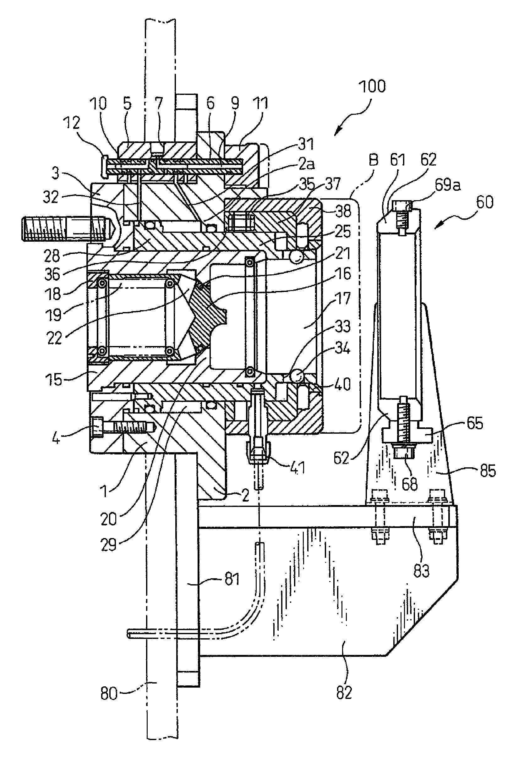
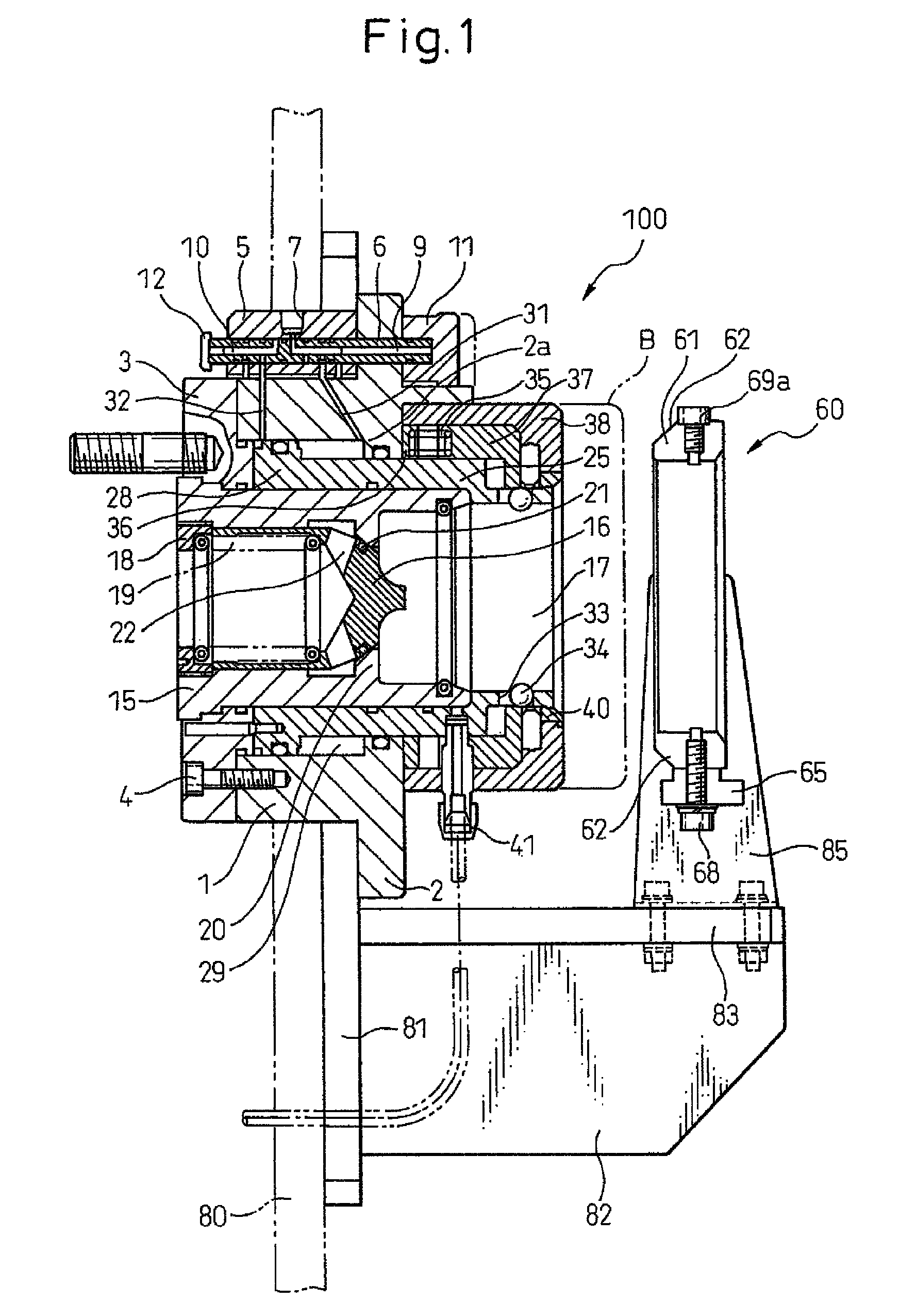
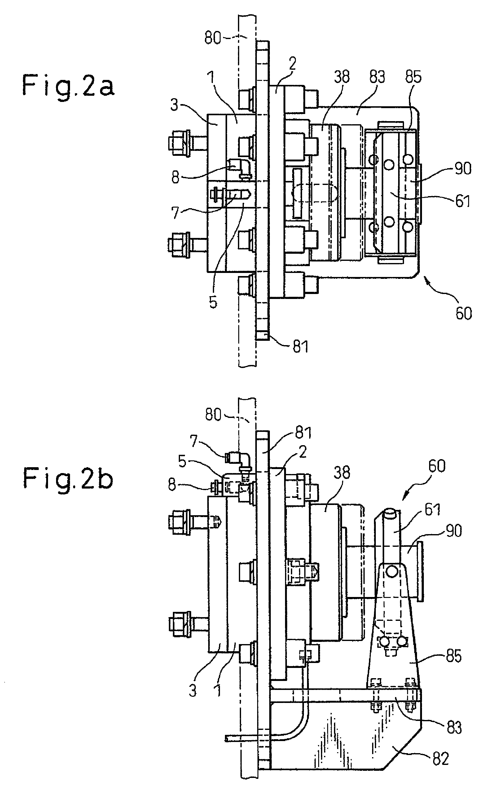
[0039]FIG. 1 is a longitudinal sectional view of a fluid-transfer coupling device in accordance with the present invention. FIG. 2a and FIG. 2b are top and side views of a socket of the fluid-transfer coupling device of FIG. 1. Further, FIG. 3 is a front view of the socket of the fluid-transfer coupling device of FIG. 1.

[0040]As shown in FIG. 1, the socket 100 of the coupling device includes a housing 1 provided, on one end thereof, with a flange 2. The other end of the housing 1 is fixed to an annular base 3 by a plurality of bolts 4. Above the housing 1, there is a shaft housing 5 that is fixed tightly to the flange 2. A shaft 6 is slidably inserted into the shaft housing 5 while penetrati...


PUM


Abstract

A fluid-transfer coupling device includes a cylindrical housing (1), a cylindrical slider (25), which contains a valve sleeve (15) accommodating a valve (16) to be opened by pressure and which can slide in the cylindrical housing and plug supporting means (60), which supports a plug (70) on condition of being drawn up to an advanced end in the valve sleeve by the movement of the slider. With this constitution, even when using a coupling device having a relatively-large diameter, it is possible to supply fluid stably. Further the plug supporting means is arranged in front of the forward end of the slider. Additionally, the plug supporting means is provided with an improper connection preventing mechanism (68, 69a to 69d, 77) for preventing other plugs, except for a specified plug from being connected.

Description

TECHNICAL FIELD[0001]The present invention relates to a fluid-transfer coupling device which is used in transferring various liquids (e.g. highly-pure chemical liquids), gas and other fluids, all of which are used in manufacturing semiconductors, from a pharmaceutical manufacturer to a container of a transport truck or transferring them from a transport container to a semiconductor production plant or a FPD (Flat Panel Display) plant.BACKGROUND OF ART[0002]Generally, a coupling device includes an immovable socket (female coupler) and a movable plug (male coupler) both of which are arranged on an identical axis line. In the coupling device, the plug is inserted into the socket, providing a liquid-tight coupled state between the plug and the socket.[0003]If such a coupling device has a relatively-small diameter, no problems occur when an operator connects the plug to the socket manually. On the contrary, if the coupling device has a relatively-large diameter, then it becomes difficult...

Claims


Application Information

Patent Timeline
Patent Type & Authority Patents(United States)
IPC IPC(8): F16L37/18
CPCF16L37/40F16L2201/20Y10T137/87973F16L37/08F16L37/23F16L37/28F16L37/32
Inventor HASUNUMA, MASAHIRO
Owner SURPASS IND
Why Eureka
Try Eureka