Electric motor control system, series hybrid vehicle, electric motor control apparatus, and electric motor control method

a technology of electric motor control and control apparatus, which is applied in the direction of field or armature current control, electric devices, gas pressure propulsion mounting, etc., to achieve the effect of increasing system efficiency and lowering engine speed

Active Publication Date: 2011-02-15
HITACHI IND PROD LTD
View PDF17 Cites 50 Cited by
  • Summary
  • Abstract
  • Description
  • Claims
  • Application Information

AI Technical Summary

Benefits of technology

Meanwhile, a strong demand for lowering the engine speed in a no drive mode and increasing a system efficiency in a drive mode is given to the batteryless series hybrid vehicle for mining or construction use.
In order to reduce a switching loss generated in the inverter in the drive mode, one-pulse control is used in most of the speed region. In the region under the one-pulse control, variations in the DC voltage correspond, as they are, to variations in the amplitude of the AC voltage applied to the motor.
It is therefore an object of the present invention to provide an electric motor control system in which the torque of an AC motor can follow up a target torque even when a DC voltage varies; and also to provide a series hybrid vehicle, an electric motor control apparatus, and an electric motor control method, based on the system.
In the aspect of the invention, the power converter is controlled by predicting a change in the DC voltage. An excitation magnetic flux component (d-axis component) varies with a first order lag with respect to a voltage applied to the AC motor, but the voltage applied to the AC motor is varied faster by an excitation time constant. This can eliminate a deviation between the d-axis excitation magnetic flux component and an excitation magnetic flux generated in the motor. Further, the d-axis excitation magnetic flux component is passed through a first order delay circuit of an excitation time constant to find a d-axis magnetic flux estimated value. A torque current command (q-axis component) is set to have a value obtained by dividing the target torque by the d-axis magnetic flux estimated value. The motor torque is proportional to a product of the excitation magnetic flux component (d-axis component) and the torque current command (q-axis component). Accordingly, even when the DC voltage applied to the power converter varies, the motor torque can follow up the target torque.

Problems solved by technology

However, since the prior art motor control means fails to consider the response first order lag in the excitation magnetic flux component (d-axis component), the means has a problem that the motor torque proportional to a product of the excitation magnetic flux and the motor current is changed later than the torque command.

Method used


Image

  • Electric motor control system, series hybrid vehicle, electric motor control apparatus, and electric motor control method
  • Electric motor control system, series hybrid vehicle, electric motor control apparatus, and electric motor control method
  • Electric motor control system, series hybrid vehicle, electric motor control apparatus, and electric motor control method

Examples


first embodiment

Prior to explanation of an electric motor controller as one of features of the present embodiment, explanation will be made as to a series hybrid vehicle.

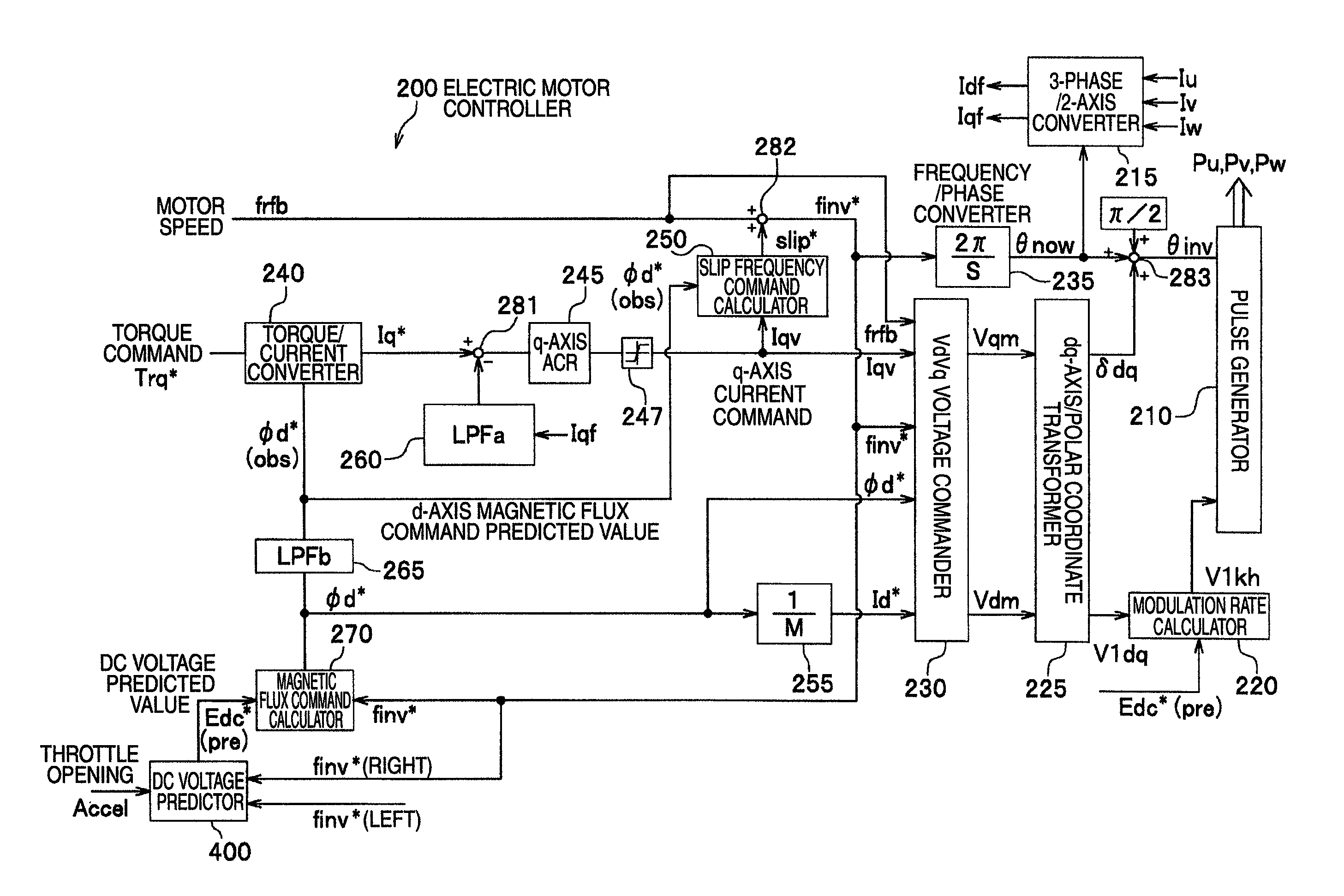
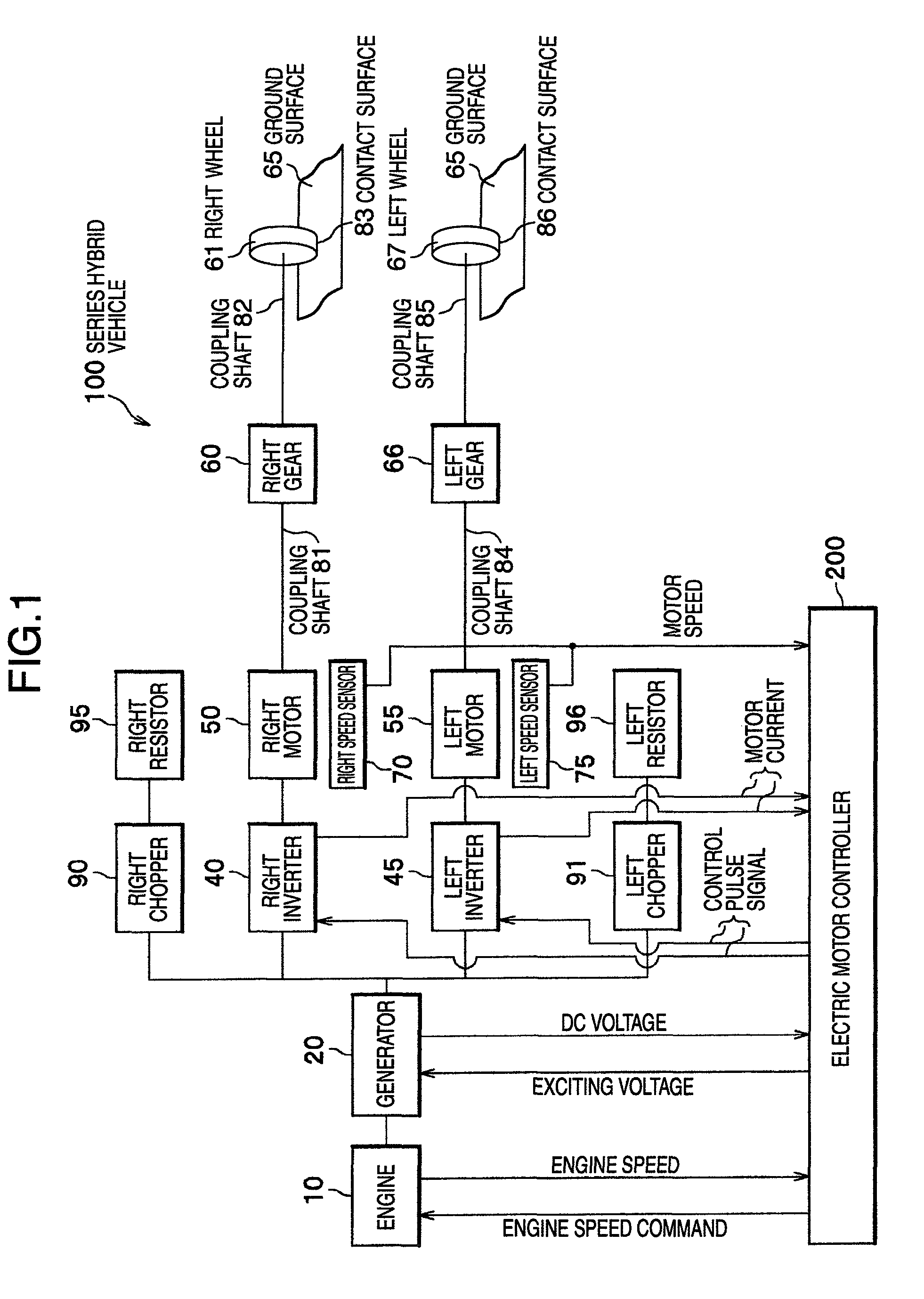
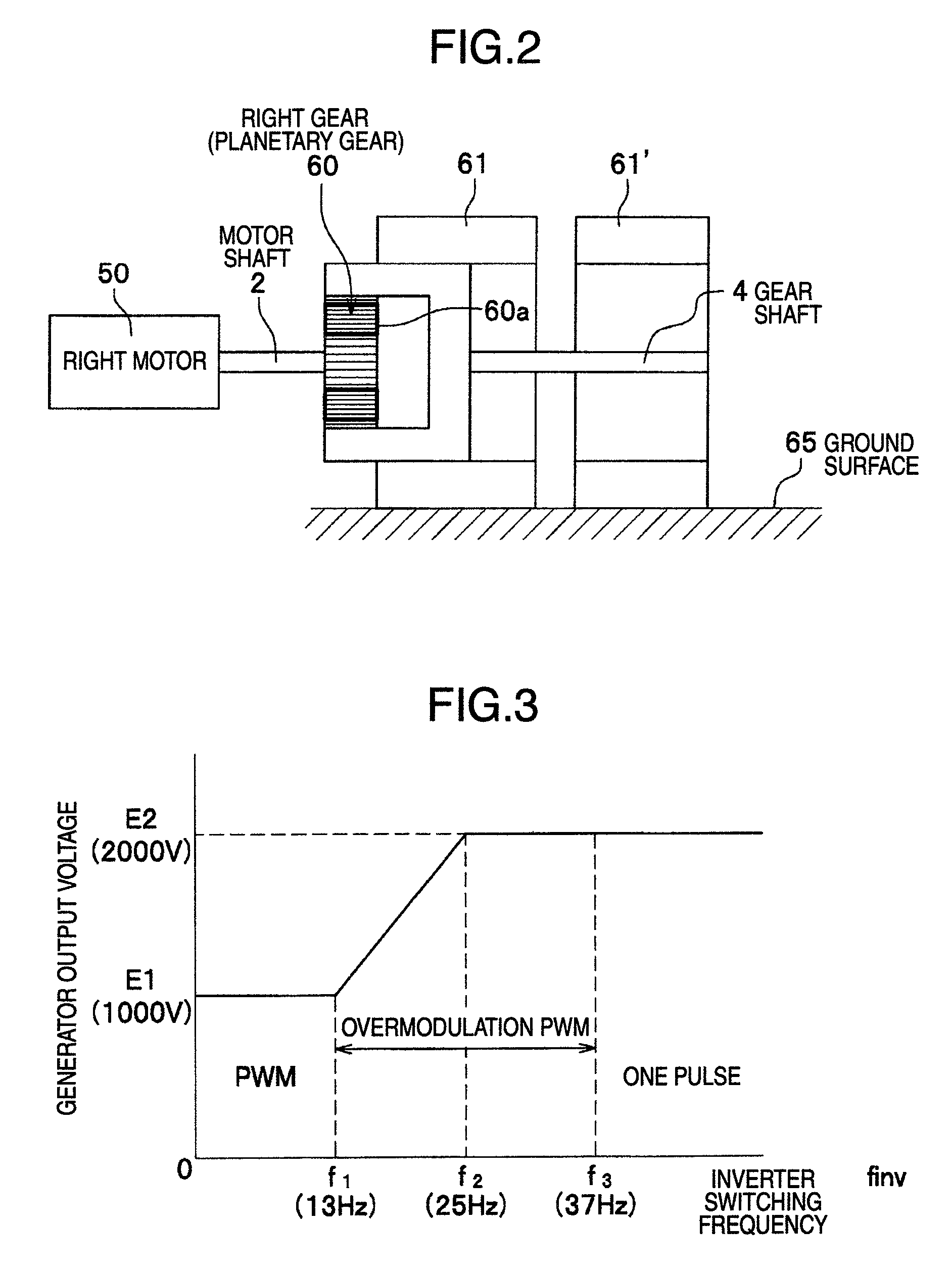
In an arrangement of FIG. 1, a series hybrid vehicle 100 in accordance with the first embodiment of the present invention includes an engine 10 for inputting an engine speed command indicative of an amount of depression in an accelerator pedal (not shown) or in a brake pedal to be rotated at an engine speed based on the command, a generator 20 coupled to the engine 10 and having a rectifier, a right inverter 40 as a power converter for converting a DC voltage generated and rectified by the generator 20 to a rectangular wave voltage, a right motor 50 as an AC motor driven by the right inverter 40, a right gear 60 (planetary gear) directly coupled to the right motor 50, a right wheel 61 directly coupled to the right gear 60, and a motor controller 200 as a motor control device. In the illustrated example, the right inverter 40, the r...

second embodiment

In the first embodiment, the DC voltage predicted value Edc*(pre) has been calculated using the future engine speed predicted value Neng*(pre), but the follow-up performance of the weak excitation characteristic involved by the change of the inverter frequency finv has not been improved. In the second embodiment, a DC voltage predicted value Edc*(pre) is further calculated using an inverter frequency predicted value finv*(pre). The inverter frequency predicted value finv*(pre) can be calculated using an observer. Other arrangement is the same as the first embodiment.

In an arrangement of FIG. 8, the inverter frequency finv* applied to the magnetic flux command calculator 270 and the DC voltage predictor 400 is different from FIG. 4 in that a motor speed observer 300 calculates the inverter frequency finv*. The motor speed observer 300 inputs a vehicle body weight Mass(fb), the torque command Trq*, and the motor speed command value finv*. The motor speed observer 300 includes a motor ...


PUM


Abstract

An electric motor control system including a generator, an AC motor, a power converter for driving the AC motor using a DC output voltage of the generator, and an electric motor controller for controlling the power converter. The electric motor controller controls the power converter by predicting a change in the DC voltage.

Description

BACKGROUND OF THE INVENTIONThe present invention relates to an electric motor control system which drives an electric motor based on the prediction of a change in the DC voltage applied to a power converter; and also a series hybrid vehicle, an electric motor control apparatus, and an electric motor control method, based on the electric motor control system.As disclosed in JP-A-2000-166009, there is known a series hybrid vehicle which includes an engine, an electric motor coupled to the engine and having a rectifier, a battery for being charged with an DC output of the motor, an inverter for converting a DC power charged by the battery into an AC power, an electric motor driven by a rectangular wave voltage generated by the inverter, and a drive mechanism for transmitting an output of the electric motor to wheels.Since driving or tractive forces of mining or construction vehicles are extremely larger as compared with those of passenger cars, the mining or construction vehicle is gen...

Claims


Application Information

Patent Timeline
Patent Type & Authority Patents(United States)
IPC IPC(8): H02P3/00H02P5/00B60L50/13
CPCB60K6/46B60L7/18B60L11/123B60L15/025B60W10/08B60W30/18172B60W30/192B60L2220/12B60L2220/14B60W20/00Y02T10/6217Y02T10/643Y02T10/646Y02T10/7005Y02T10/7077Y02T10/84Y02T10/648B60L50/61Y02T10/62Y02T10/64Y02T10/70H02P3/00Y02T10/7072
Inventor SUGAWARA, NAOSHIFUJIMOTO, TETSUHIROKIYOFUJI, YASUHIROSHIMADA, KEIZOKIKUCHI, AKIRAIMAIE, KAZUHIRO
Owner HITACHI IND PROD LTD
Why Eureka
Try Eureka