K-space trajectory estimation in spiral MRI system and related method thereof

a spiral mri and trajectory technology, applied in the field of mr imaging, can solve the problems of severe image artifacts, inability to measure the k-space trajectory for each imaging slice, and inability to accurately reconstruct images, etc., to achieve the effect of simple and effective, reducing the root mean square error (rmse) and peak error in phantom images reconstructed using the proposed method

Active Publication Date: 2011-02-15
VIRGINIA UNIV OF
View PDF17 Cites 33 Cited by
  • Summary
  • Abstract
  • Description
  • Claims
  • Application Information

AI Technical Summary

Benefits of technology

[0006]Here we introduce a simple and effective model to estimate the k-space trajectory in spiral image reconstruction with the measured k-space trajectory as the goal. The ro...

Problems solved by technology

For non-2DFT data acquisition in MRI, k-space trajectory infidelity due to eddy current effects and other hardware imperfections will blur and distort the reconstructed images.
Even with the shielded gradients and eddy current compensation techniques of current scanners, the deviation between the actual k-space trajectory and the requested trajectory remains a major reason for image artifacts in non-Cartesian MRI.
However, it is usually not practical to measure the k-space trajectory for each imaging slice.
Howeve...

Method used


Image

  • K-space trajectory estimation in spiral MRI system and related method thereof
  • K-space trajectory estimation in spiral MRI system and related method thereof
  • K-space trajectory estimation in spiral MRI system and related method thereof

Examples


Embodiment Construction

[0016]A preferred embodiment of the present invention will now be set forth in detail with reference to the drawings.

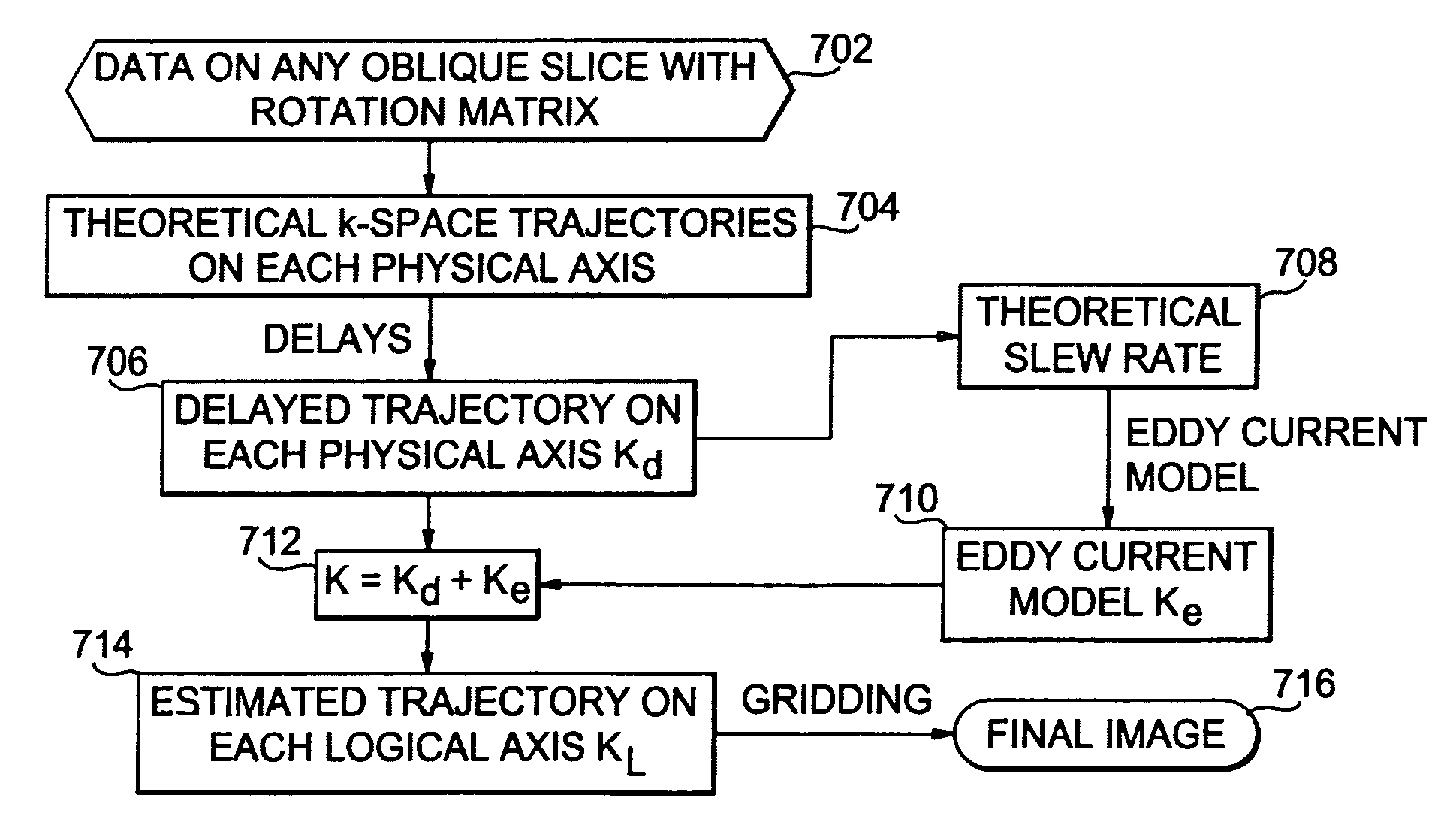
[0017]First, we collect data on two thin slices offset symmetrically around isocenter for coronal, sagittal and transverse views. The B0 eddy currents are then measured using the method proposed by Gurney et al. [P. Gurney, J. Pauly, D. G. Nishimura, “a simple method for measuring B0 eddy currents”, Proc. ISMRM, 13: 866 (2005)] and deducted from the corresponding phase term. Dividing the corrected signal phase by the slice distance, we get the measured k-space trajectories Kb in each view for calibration purposes. Dividing the corrected signal phase by the slice distance, we get the actual k-space trajectories Kb on each physical gradient axis in each view as follows for calibration purposes:

Kb=[(P+)(g+)−P+(g−))−(P−(g+)−P−(g−))] / (4D)

[0018]where P±( ) are the phase terms in two symmetrical slices; g± are the gradient waveform to be tested and its inverted version; D is...


PUM


Abstract

First, benchmark data are collected on two thin slices of an object to get measured k-space trajectories. To find delays on different physical gradients, the root mean square error between estimated and measured k-space trajectories is minimized for different delays. To reduce the error further, an eddy current compensation is introduced along each physical gradient axis. A more accurate estimation of the k-space trajectory can be obtained to image the object.

Description

REFERENCE TO RELATED APPLICATION[0001]The present application claims the benefit of U.S. Provisional Patent Application No. 60 / 903,143, filed Feb. 23, 2007, whose disclosure is hereby incorporated by reference in its entirety into the present disclosure.STATEMENT OF GOVERNMENT INTEREST[0002]The work leading to the present invention was supported by NIH Grant No. R01 HL079110. The government has certain rights in the invention.FIELD OF THE INVENTION[0003]The present invention is directed to magnetic resonance (MR) imaging and more specifically to k-space trajectory estimation using an anisotropic gradient delay model.DESCRIPTION OF RELATED ART[0004]For non-2DFT data acquisition in MRI, k-space trajectory infidelity due to eddy current effects and other hardware imperfections will blur and distort the reconstructed images. Even with the shielded gradients and eddy current compensation techniques of current scanners, the deviation between the actual k-space trajectory and the requested...

Claims


Application Information

Patent Timeline
IPC IPC(8): G01V3/00
CPCG01R33/56518G01R33/56572G01R33/4824
Inventor TAN, HAOMEYER, CRAIG H.
Owner VIRGINIA UNIV OF
Why Eureka
Try Eureka