
Analysis of optical data with the aid of histograms

a technology of optical data and histograms, applied in the field of optical analysis, can solve the problems of high degree of inaccuracy of measured glucose, low accuracy of measurement results, and inability to meet the size of measured sections required for error-free measurement, etc., to achieve the effect of reducing space requirements, reducing the amount of data, and reducing memory requirements

Active Publication Date: 2011-02-15
ROCHE DIABETES CARE INC
View PDF31 Cites 9 Cited by
  • Summary
  • Abstract
  • Description
  • Claims
  • Application Information

AI Technical Summary

Benefits of technology

The patent describes a system for measuring the concentration of a substance in a small amount of liquid. The system uses a detection area that is wetted or not wetted by the liquid. The system analyzes the light intensity on the detection area and selects the highest intensity as the concentration of the substance. The system can measure with high accuracy even small amounts of liquid. It is particularly useful for measuring blood samples from patients with diabetes. The system uses a histogram to analyze the frequency distribution of the light intensity and identify areas of the detection area that are not affected by secondary effects. The system can be manufactured and operated more cost-effectively than conventional devices.

Problems solved by technology

Non-uniform or inadequate wetting of the detection area can result in erroneous results.
Especially when a small amount of test liquid is used, the distribution on the test element may not be uniform and only a part of the detection area is wetted with sample material.
In the conventional optically-based methods of measurement the reflected light is often measured from the entire detection area which results in a high degree of inaccuracy of the measured glucose because different proportions of unwetted area enter into the determination depending on the applied amount of sample.
Thus, if the detection area is inadequately wetted it may fall short of the size of measured section required for an error-free measurement.
Attempts to overcome inadequate or non-uniform wetting of the test element have previously not led to a satisfactory solution.
This is not easy especially in the case of diabetics who often already have a reduced vision.

Method used


Image

  • Analysis of optical data with the aid of histograms
  • Analysis of optical data with the aid of histograms
  • Analysis of optical data with the aid of histograms

Examples


Embodiment Construction

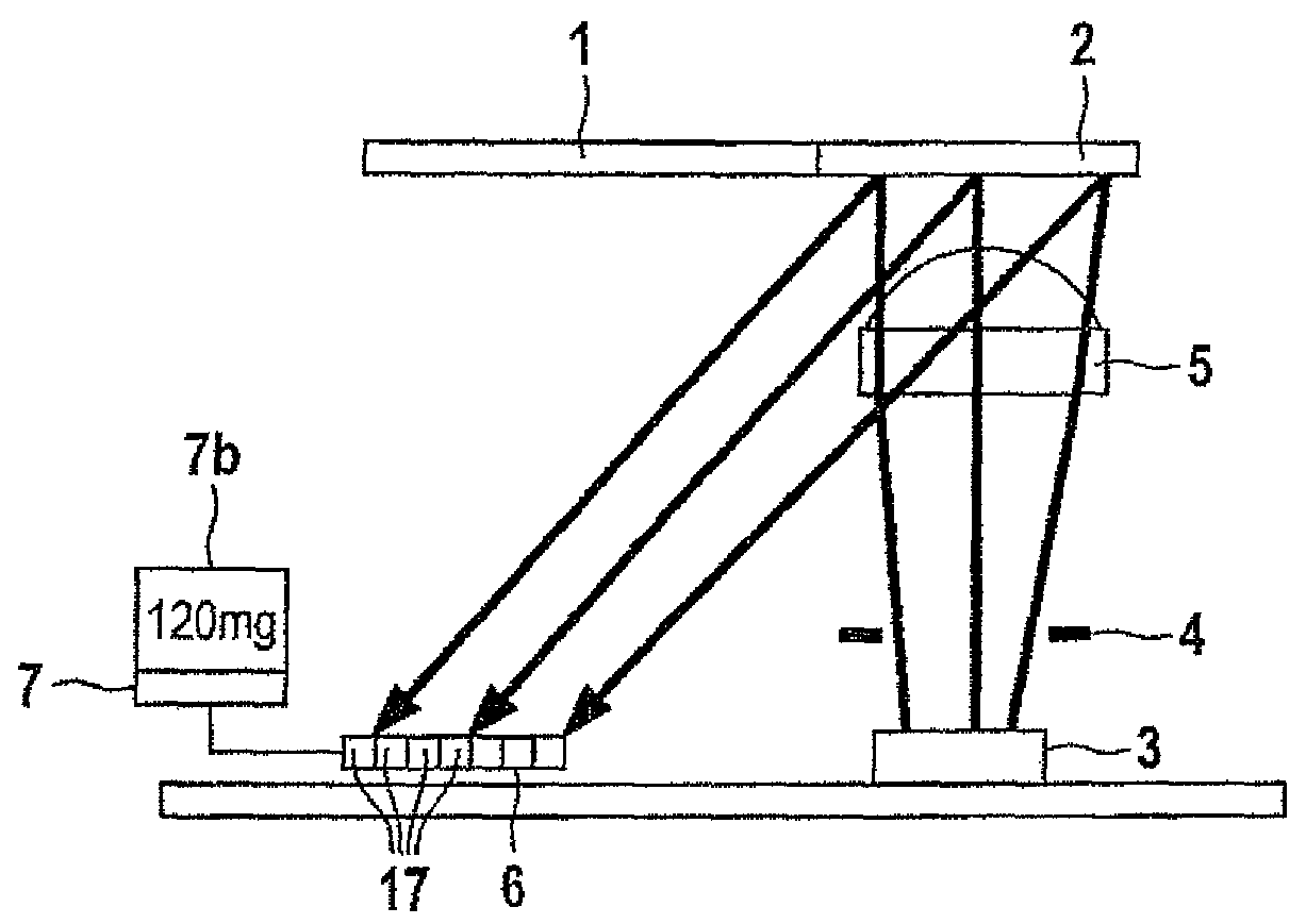
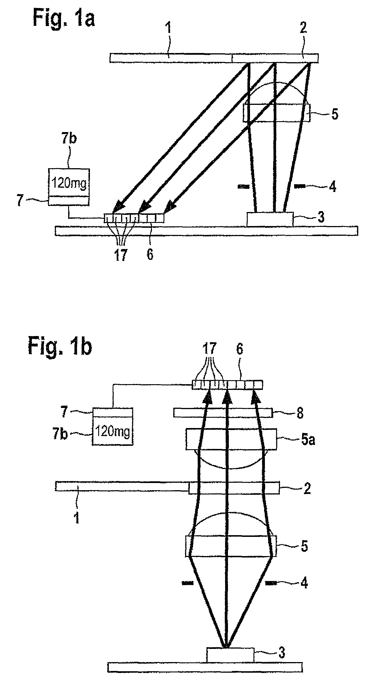
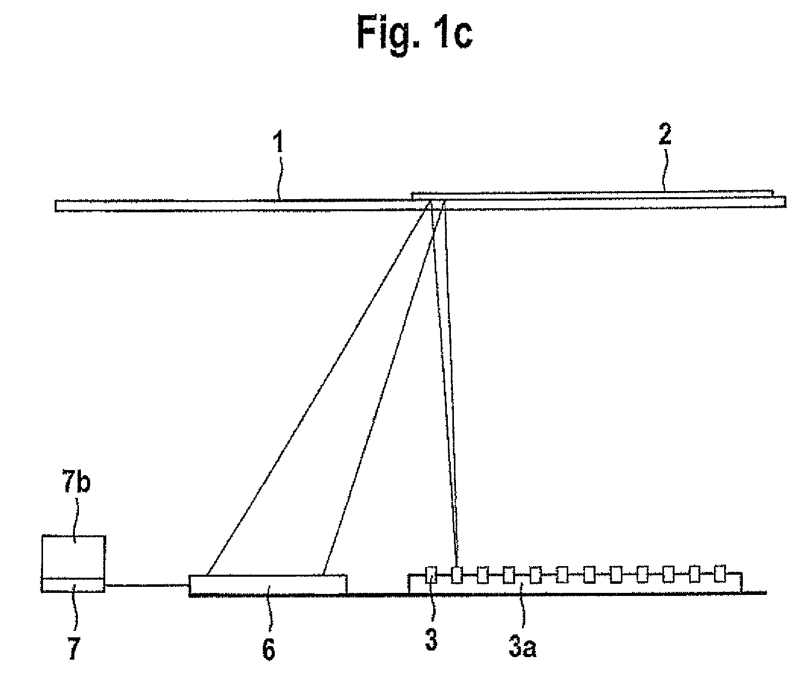
[0069]FIG. 1a shows a system which contains a test element (1) with a detection area (2) which is irradiated by a light source (3). Imaging units such as for example lenses and / or diaphragms can be mounted between the light source (3) and the test element (1). In this example a diaphragm (4) and also a lens (5) are arranged between the light source and detection area (2) of the test element (1) in order to illuminate the detection area (2) as homogeneously as possible. The light radiated from the detection area (2) is captured by a detector (6). This detector (6) should comprise at least 10 pixels (17) in order to be able to detect the detection area (2) in a spatially-resolved manner. The signals of the detector (6) are analysed in an evaluation unit (7) which is connected to the detector (6). A preferred embodiment of the detector is a CMOS detector which comprises at least one A / D converter in order to convert the analogue electrical signals into digital signals. These digital si...


PUM

PropertyMeasurementUnit
volumeaaaaaaaaaa
volumeaaaaaaaaaa
volumesaaaaaaaaaa

Abstract

A system for determining the concentration of an analyte in a liquid sample comprising a detection unit for detecting light intensities which are radiated from subareas of a detection area of a test element as well as an evaluation unit which determines a frequency distribution for the detected light intensities wherein the frequency distribution has at least one first maximum caused by unwetted subareas or at least one reference area and a second maximum caused by wetted subareas and selects at least one light intensity on the basis of the frequency distribution and determines the concentration of the analyte from the at least one selected light intensity.

Description

RELATED APPLICATION[0001]This application is a continuation of PCT / EP07 / 002968, filed Apr. 3, 2007, the entire disclosure of which is expressly incorporated herein by reference.TECHNICAL FIELD[0002]The present disclosure relates to the field of optical analysis of small sample volumes such as those which for example occur when diagnosing blood samples.BACKGROUND[0003]The determination of the concentration of various analytes in physiological samples is of growing importance in our society. Such samples are analysed in various fields of application for example in clinical laboratories or in “home monitoring”. In particular this also includes glucose measurement in diabetes management and the measurement of cholesterol for cardiac and vascular diseases. Medical blood diagnostics always requires that a blood sample is collected from the individual to be examined.[0004]The analytics carried out after the lancing process are often carried out in a small portable measuring instrument a so...

Claims


Application Information

Patent Timeline
Patent Type & Authority Patents(United States)
IPC IPC(8): G01N33/48G01N21/00G01N21/55G01V8/00G01N21/86A61B5/00G01J3/46G01N21/75
CPCG01N21/8483G06T7/0012G06T7/401G06T2207/10056G06T2207/30024G06T7/41
Inventor PETRICH, WOLFGANGHAAR, HANS-PETERASFOUR, JEAN-MICHELKOCHERSCHEIDT, GERRIT
Owner ROCHE DIABETES CARE INC
Learn More