Color filter inspection method, color filter manufacturing method, and color filter inspection apparatus

a color filter and manufacturing method technology, applied in the direction of optical apparatus testing, instruments, optical elements, etc., can solve the problem of inability to detect the cause of luminance unevenness, and achieve the effect of reducing manufacturing costs, facilitating luminance differences, and highly accurate detection of unevenness

Inactive Publication Date: 2011-02-15
SHARP KK
View PDF51 Cites 1 Cited by
  • Summary
  • Abstract
  • Description
  • Claims
  • Application Information

AI Technical Summary

Benefits of technology

[0012]According to the foregoing method, the color filter edge, containing a boundary between the pixel and the black matrix, where unevenness is likely to occur in a drying step or the like is illuminated at an appropriate angle, and light reflected at an angle different from an angle of specular reflection of light is imaged. Therefore, as with the technique of Patent Document 1, which uses diffuse reflected light, the imaging system is hardly struck by light reflected by a part other than the color filter edge. This makes it easy to make a difference in luminance within an image taken by the imaging system.
[0031]The foregoing method detects the occurrence of unevenness at any stage in a color filter manufacturing step (such as a drying step) and feeds back the information to the color filter manufacturing apparatus, thereby preventing a defective product from entering the inspection step or the step subsequent thereto. This enables improvement in yield of liquid crystal displays, thus enabling a reduction in manufacturing cost.

Problems solved by technology

However, the image, obtained by imaging the diffuse reflected light, which is used by the conventional method of Patent Document 1 has no grayscale produced therein.
This undesirably makes it impossible to detect a cause of unevenness of luminance, i.e., a change in shape near a boundary between the color filter and a black matrix.

Method used


Image

  • Color filter inspection method, color filter manufacturing method, and color filter inspection apparatus
  • Color filter inspection method, color filter manufacturing method, and color filter inspection apparatus
  • Color filter inspection method, color filter manufacturing method, and color filter inspection apparatus

Examples


Embodiment Construction

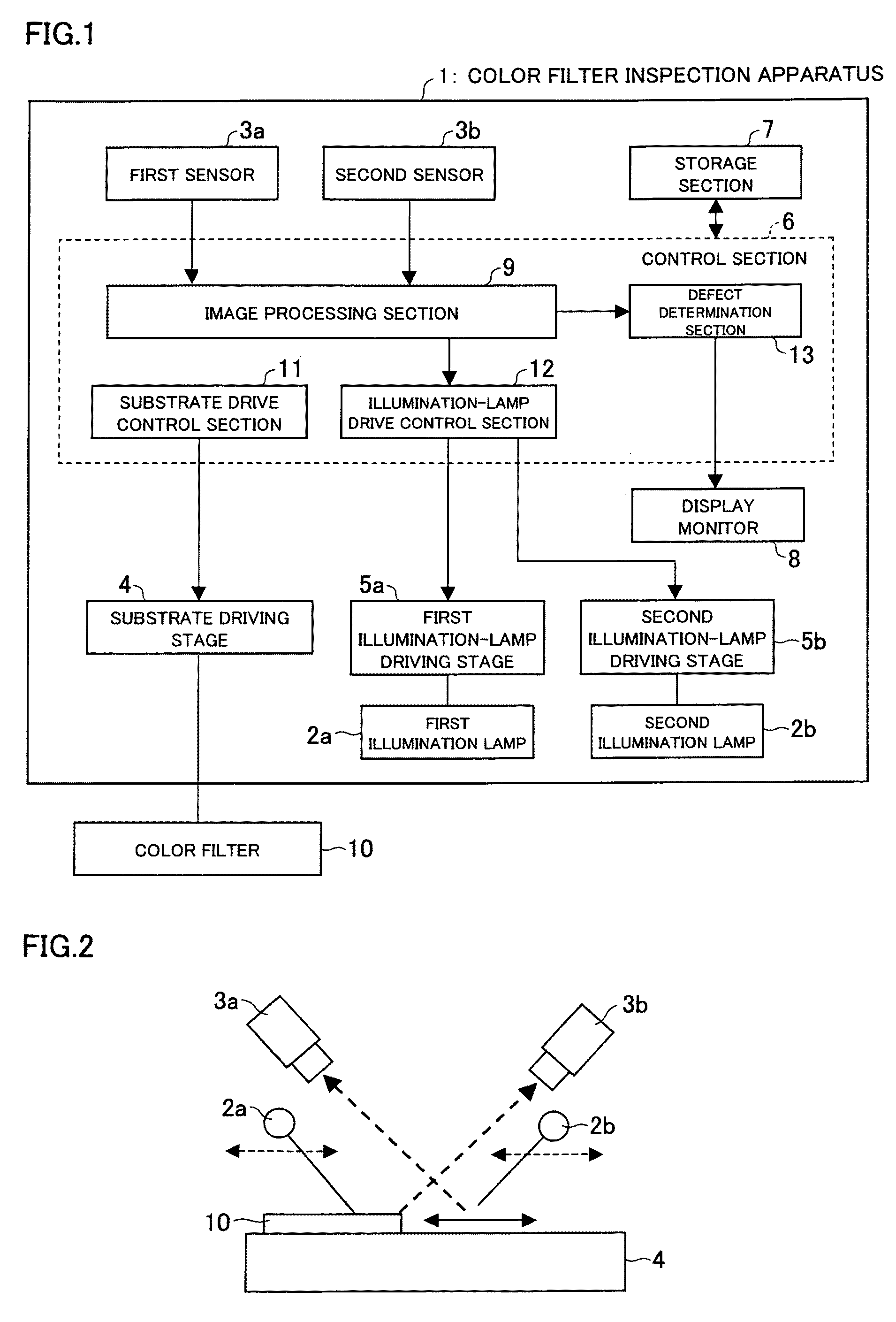
[0083]A color filter inspection method, a color filter inspection apparatus, a color filter manufacturing method each according to the present invention will be described below in various embodiments with reference to FIGS. 1 through 17.

[0084]FIG. 1 is a block diagram showing an arrangement of a color filter inspection apparatus 1 according to the present embodiment. As shown in FIG. 1, the color filter inspection apparatus 1 includes an illumination lamp (illuminating means) 2, a sensor (imaging means) 3, a substrate driving stage 4, an illumination-lamp driving stage 5, a control device 6, a storage section 7, and a display monitor 8. The control section 6 includes an image processing section (shot-image information analyzing means) 9, a substrate drive control section 11, and an illumination-lamp drive control section 12, and a defect determination section (unevenness determining means) 13. The substrate driving stage 4 has a color filter 10 mounted thereon.

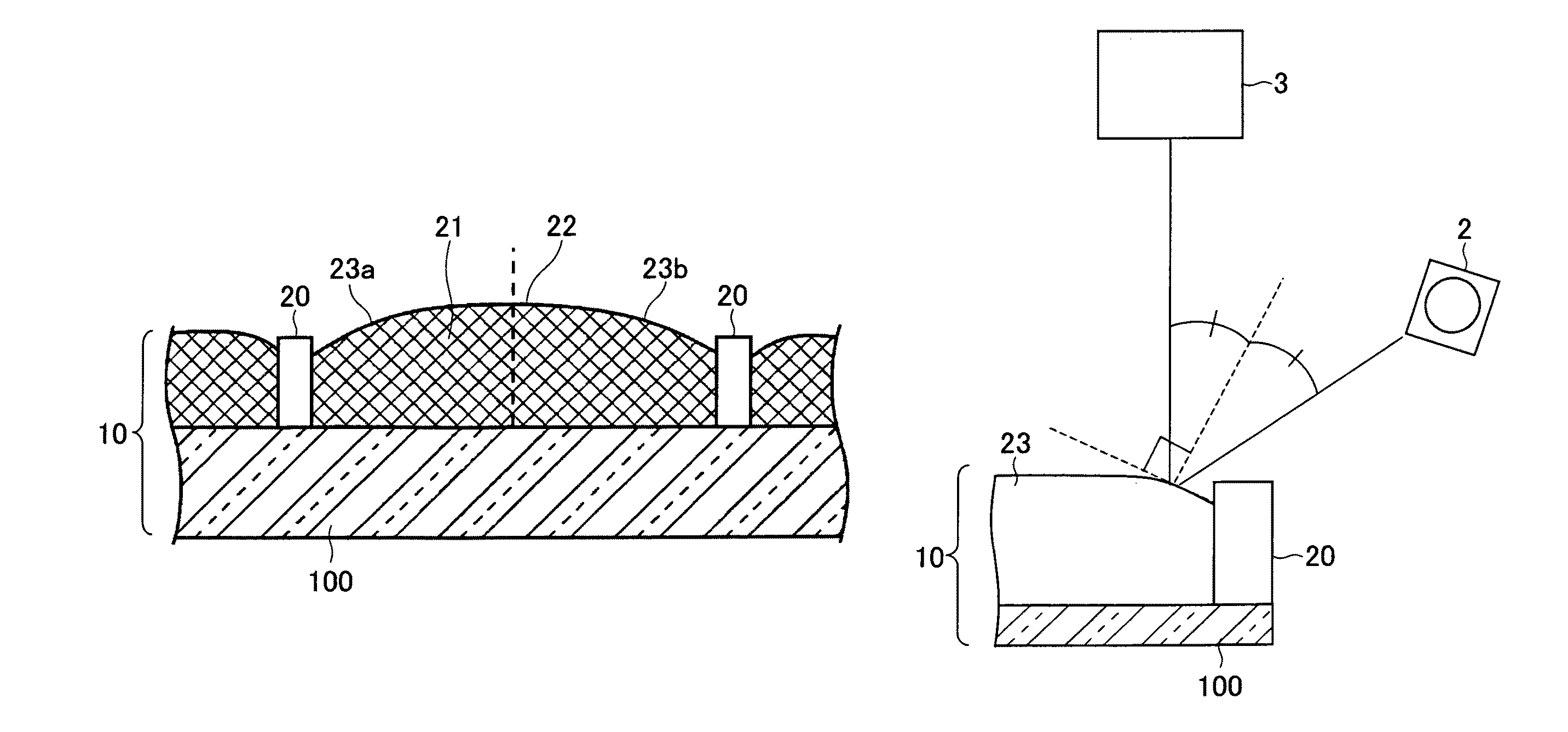
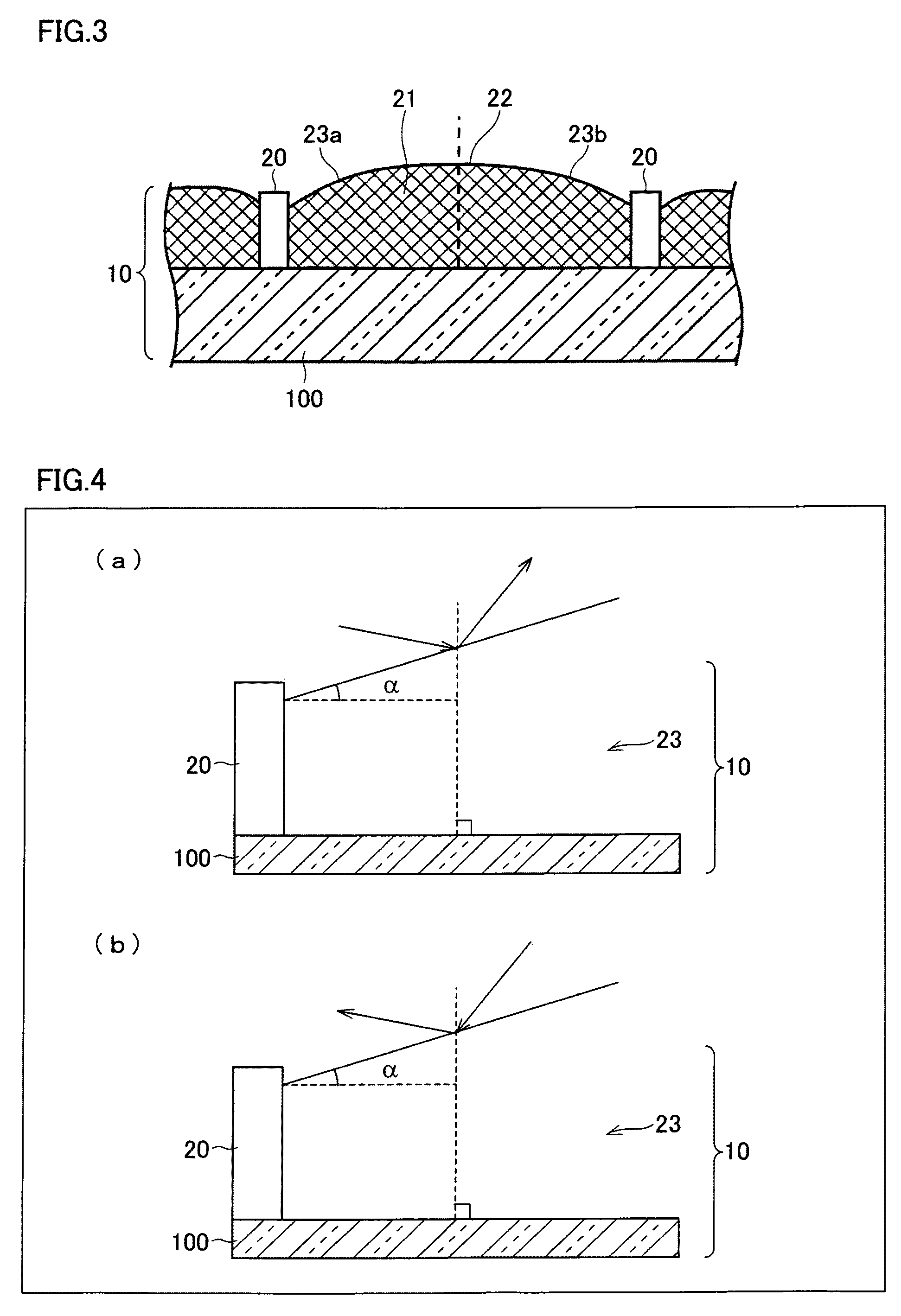
[0085]Further, FIG. 2 ...


PUM


Abstract

Included are an illumination lamp (2) for illuminating a color filter edge (23) at a predetermined angle of incidence, a sensor (3) for taking at least two images by imaging light reflected at a predetermined angle different from the angle of incidence, an image processing section (9) for calculating a difference in luminance within a color filter in accordance with the images thus taken, and a defect determination section (13) for determining the existence of unevenness in the color filter from the difference in luminance. Provided thereby are a color filter inspection method and a color filter inspection apparatus, each for early discovering unevenness through macroscopic observation of the whole color filter by illuminating the color filter edge and by taking reflected light that is not specular reflected light, the unevenness occurring in a drying step, the color filter edge containing a boundary between a pixel and a black matrix. Further provided is a method for manufacturing a color filter with use of the color filter inspection method.

Description

TECHNICAL FIELD[0001]The present invention relates to methods for inspecting, for unevenness, color filters of liquid crystal displays for use in color televisions, personal computers, and the like, methods for manufacturing color filters with little unevenness, and apparatuses for inspecting color filters for unevenness. In particular, the present invention relates to a color filter inspection method and the like for early detecting, through macroscopic observation of a color filter, unevenness that occurs in a color filter manufacturing step such as a drying step.BACKGROUND ART[0002]In recent years, liquid crystal display devices have been made larger, and there has been a tendency toward a growing demand for large liquid crystal display devices. However, cost reduction is required for further widespread use. Accordingly, there has been a growing demand for cost reduction in color filters, for color filters are high in cost ratio. In particular, it is important to raise yields, fo...

Claims


Application Information

Patent Timeline
Patent Type & Authority Patents(United States)
IPC IPC(8): G01B11/28
CPCG01M11/00G01N21/8806G01N21/95G01N2021/8887G01N2021/9513G02B5/201G02F1/133516
Inventor ITOH, KENJI
Owner SHARP KK
Why Eureka
Try Eureka