
Method and apparatus for identifying a failure mechanism for a component in a computer system

a failure mechanism and computer system technology, applied in the direction of instruments, nuclear elements, diagnostic recording/measuring, etc., can solve problems such as system failure, lack of ability, and inability to provide correct solutions for dealing with faults

Active Publication Date: 2011-02-15
ORACLE INT CORP
View PDF9 Cites 11 Cited by
  • Summary
  • Abstract
  • Description
  • Claims
  • Application Information

AI Technical Summary

Benefits of technology

Automatically identifies failure mechanisms in computer systems, enabling proactive fault management and reducing the need for continuous human monitoring by accurately matching telemetry signals with known failure patterns.

Problems solved by technology

Typically, this is achieved by detecting anomalies in the signals which may potentially lead to system failures.
Unfortunately, a monitoring system that lacks the ability to identify the root cause of a fault cannot provide correct solutions for dealing with the fault.
However, it is not possible to have humans looking at these telemetry signatures on a 24×7 basis.

Method used


Image

  • Method and apparatus for identifying a failure mechanism for a component in a computer system
  • Method and apparatus for identifying a failure mechanism for a component in a computer system
  • Method and apparatus for identifying a failure mechanism for a component in a computer system

Examples


example

[0050]FIG. 5 illustrates an exemplary process for identifying a root cause for a faulty power supply in a server system in accordance with an embodiment of the present invention.

[0051]A known type of degradation in this type of power supplies is characterized by distinctive and reproducible transients in the output voltages which contain a characteristic pattern: a dip followed by a spike. Unfortunately, the time series telemetry signals obtained from these power supplies contain only low-resolution, low-sampling-rate signal values. This low-resolution, low-sampling rate time series contains an incomplete version of the actual failure signature, which is shown in FIG. 5A.

[0052]Note that it is typically difficult to evaluate the characteristics, such as amplitude and duration of the transient behavior based on such noisy and incomplete information.

[0053]However, by using an auto-associative memory, one is able to reconstruct (recall) the complete failure signature of the recorded tra...


PUM


Abstract

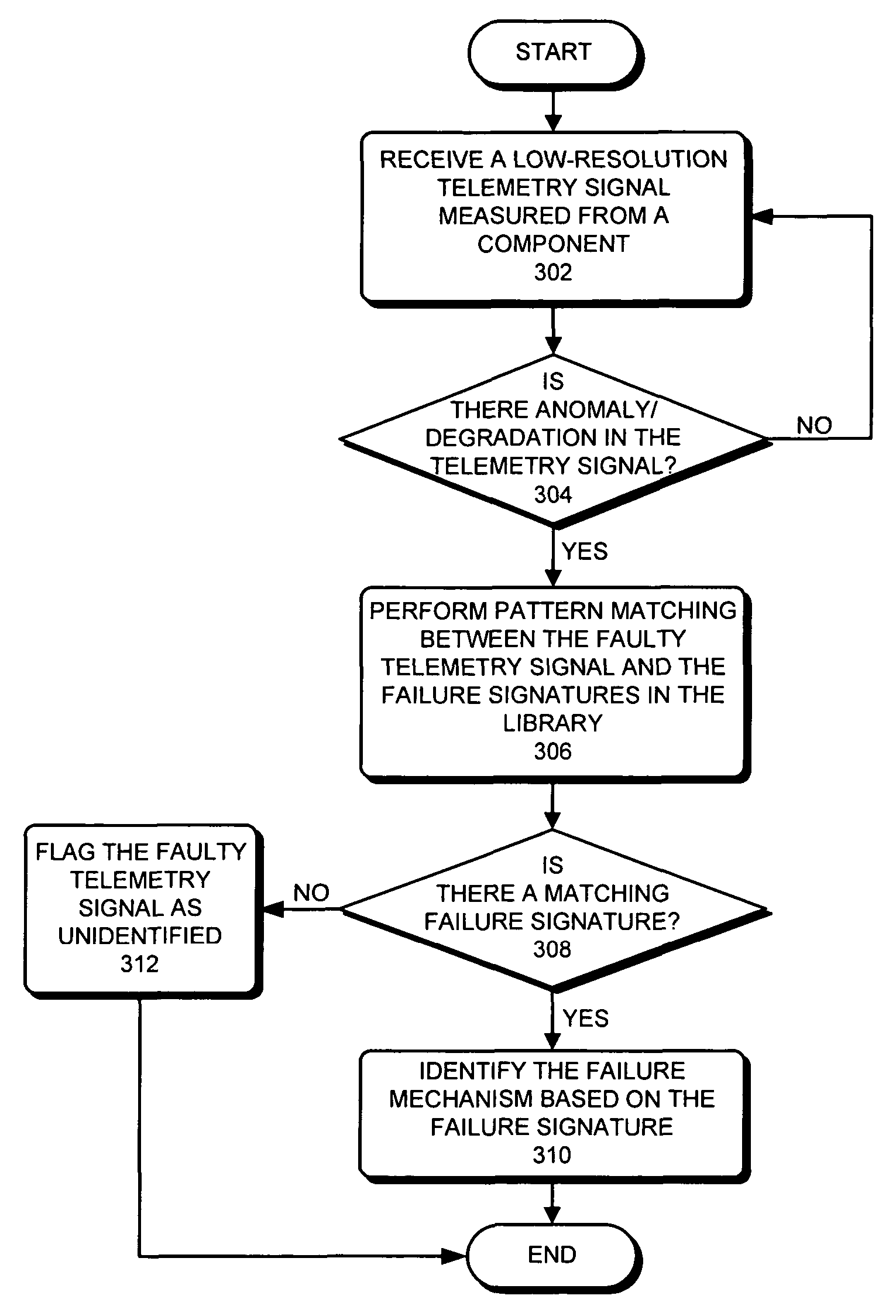
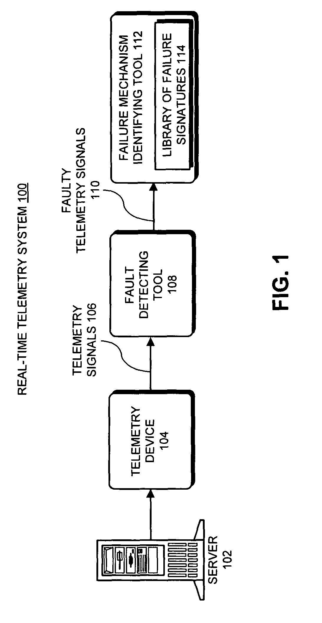
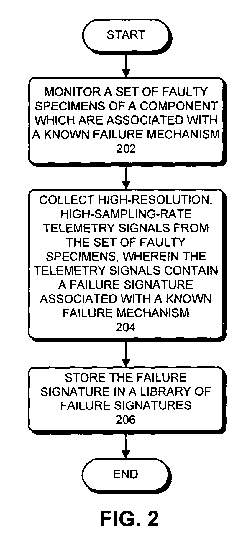
One embodiment of the present invention provides a system that identifies a failure mechanism for a component. The system first constructs a library of failure signatures from a set of components, wherein each failure signature in the library characterizes a known failure mechanism associated with a component in the set of components. Next, the system receives a telemetry signal which is measured from a component under surveillance. The system then determines if there is an anomaly in the telemetry signal. If so, the system performs pattern-matching operations between the telemetry signal and failure signatures in the library. Next, if a match is found, the system identifies the failure mechanism for the component under surveillance based on the matching failure signature.

Description

BACKGROUND[0001]1. Field of the Invention[0002]The present invention relates to techniques for performing a root-cause analysis on a faulty computer system. More specifically, the present invention relates to a method and an apparatus that automatically identifies a failure mechanism associated with a signal measured from a faulty component in a computer system.[0003]2. Related Art[0004]Modern server systems are typically equipped with a significant number of sensors which monitor signals during the operation of the server systems. For example, these monitored signals can include temperatures, voltages, currents, and a variety of software performance metrics, including CPU usage, I / O traffic, and memory utilization. Outputs from this monitoring process can be used to generate time series data for these signals which can subsequently be analyzed to determine how well a computer system is operating.[0005]One particularly useful application of this analysis technique is to facilitate “...

Claims


Application Information

Patent Timeline
Patent Type & Authority Patents(United States)
IPC IPC(8): G06F11/00
CPCG06F1/30G06F11/0748G06F11/0751G06F11/2252
Inventor USYNIN, ALEXANDER V.URMANOV, ALEKSEY M.GROSS, KENNY C.
Owner ORACLE INT CORP
Learn More