Radial rolling bearing, especially single-row deep groove rolling bearing

a technology of deep groove ball bearings and rolling bearings, which is applied in the direction of sliding contact bearings, rigid support of bearings, mechanical equipment, etc., can solve the problems of bearing cage destruction, bearing cage destruction, and bearing cages that are unsuitable for special rolling bodies, etc., to achieve cost-effective, low overall production costs, and cost-effective purchasing

Inactive Publication Date: 2011-02-22
SCHAEFFLER TECH AG & CO KG
View PDF14 Cites 11 Cited by
  • Summary
  • Abstract
  • Description
  • Claims
  • Application Information

AI Technical Summary

Benefits of technology

[0006]Proceeding from the explained disadvantages of the known prior art, the object on which the invention is based is therefore that of designing a radial rolling bearing, in particular deep-groove rolling bearing which is formed with a bearing cage which is simple and cost-effective to produce and with which, firstly, axial guidance of the rolling bodies which are embodied as spherical disks is ensured, and secondly, friction-heat-generating contact between the spherical disks and the bearing cage can be prevented even at low bearing speeds and / or under mixed axial and radial bearing loading.DESCRIPTION OF THE INVENTION
[0009]Preferably, central depressions are formed into the side surfaces of the rolling bodies, which provide an additional lubricant reservoir for the radial rolling bearing. Said central depressions are preferably formed in the manner of circular flat recesses, from which the lubricant, which is filled in during the assembly of the bearing, automatically flows out into the bearing interior space, which is preferably sealed off by means of lateral sealing rings, under centrifugal force during operation of the bearing. At the same time, said depressions have the advantage that, as a result, the mass center of gravity of the rolling bodies is moved radially outward toward their running surfaces, and the running properties of the rolling bearing are therefore significantly improved.
[0010]A further feature of the radial rolling bearing designed according to the invention is that the lines of contact between the side surfaces of the rolling bodies and the longitudinal webs of the cage pockets can preferably be produced by means of axial wedge-shaped depressions which are formed longitudinally centrally into the longitudinal webs and which extend over the width of the side surfaces of the rolling bodies. During bearing operation, said wedge-shaped depressions are not in permanent contact with the side surfaces of the rolling bodies, but in the event of guidance, are in guiding contact with said side surfaces each at two points. Furthermore, it is advantageous for the resulting wedge edge on the wedge-shaped depressions to be of rounded design in order to prevent premature wear of said wedge edge.
[0011]According Additionally, the radial rolling bearing according to the invention is also characterized in that the transverse webs, which are formed so as to be domed corresponding to the radii of the running surfaces of the rolling bodies, of the cage pockets extend at both sides beyond said running surfaces in such a way that the longitudinal webs, which are connected to said transverse webs by means of rounded transition regions, of the cage pockets are arranged with a spacing to the side surfaces of the rolling bodies. The arrangement of the longitudinal webs of the cage pockets spaced apart from the side surface has the advantage that the rolling bodies simultaneously have an axial degree of freedom, which is delimited by the upper and lower sides of the wedge-shaped depressions in the longitudinal webs, of approximately 12.degree. to 18.degree., by means of which the rolling bodies can self-align to the pressure angle of the radial bearing under radial and axial bearing loading.
[0013]The features of the radial bearing designed according to the invention finally also contribute to the achievement of the object that the bearing cage is either formed as a punched, drawn, or embossed part, which can be produced without cutting, and is composed of a metal material, or as an injection-molded part composed of an engineering plastic or high-temperature-resistant plastic or, alternatively, of a fiber-composite plastic composed of fabric reinforcement and resin matrix. In terms of the metal materials, primarily steel, brass and aluminum have been proven to be particularly suitable, with which the bearing cage can additionally be coated entirely, or limited to its contact points with the rolling bodies, with functional coatings composed of hard material, chromite, oxide ceramics or molybdenum, or encapsulated with an engineering plastic. In contrast, suitable engineering plastics for the bearing cage are PA 66 or PA 46 with or without inclusions of glass fibers, while it is possible as high-temperature-resistant plastics to use for example PAEK, PEEK, TPI or PAI with suitable additives or inclusions of glass fibers. Said materials have proven to be particularly cost-effective in purchasing terms and also permit the use of more cost-effective production processes for the bearing cage, such that radial bearings formed with bearing cages of said type can be produced with low overall production costs.
[0014]The radial rolling bearing designed according to the invention therefore has the advantage over the radial rolling bearings known from the prior art that, as a result of the formation of the bearing cage with bearing pockets in which the rolling bodies are guided axially merely by means of two double lines of contact, the kinematic conditions in a radial bearing are taken into consideration in that said radial bearing has an axial guide for the rolling bodies, by means of which the tumbling movements, or tilting movements transversely with respect to the running direction, of the rolling bodies which occur below a permissible minimum speed no longer lead to friction heat and to an impermissible increase in the operating temperature of the radial rolling bearing. At the same time, the rolling bodies have, as a result of their line-of-contact guidance in the cage pockets, a sufficient degree of freedom in the axial direction, by means of which said rolling bodies can self-align to the pressure angle of the radial rolling bearing present under radial and axial bearing loading, without coming into contact with the bearing cage. Furthermore, a bearing cage of said type has also proven to be advantageous with regard to low production costs, since said bearing cage is of structurally simple design and can be produced from cost-effective materials and using cost-effective production and assembly processes.

Problems solved by technology

In practice, however, it has been found that deep groove ball bearings of said type are nevertheless limited in terms of the load capacity of the bearing on account of the small maximum number of balls which can be installed, which is dependent on the dimensions of the inner and of the outer bearing ring and on the ball diameter.
It has however proven to be disadvantageous that a bearing cage of said design does not make allowance for the entire kinematic behavior of the rolling bodies, which are embodied as spherical disks, which occurs under different bearing loadings, and therefore said bearing cage would appear to be unsuitable for special rolling bodies of said type.
Here, the friction between the spherical disks and the bearing cage can become so intense that the permissible operating temperature of the bearing is exceeded and the required lubricating film between the spherical disks, the bearing cage and the bearing rings becomes locally separated or the lubricant is partially burned, such that the bearing cage is destroyed and the bearing fails prematurely.
It was likewise found that, with a bearing cage of said type, a similar effect which likewise leads to its destruction occurs in that it is not possible for the spherical disks, on account of their mounting between the two ring halves on the rivets of the bearing cage, to be aligned to the respective pressure angle of the radial rolling bearing under mixed radial and axial loading of the radial rolling bearing.
Finally, a bearing cage of said type for spherical disks has also proven to be disadvantageous with regard to the production costs of radial rolling bearings fitted with such bearing cages, since the production of said bearing cage, and in particular the assembly of said bearing cage which must take place into the fitted bearing by means of rivets, is relatively complex.

Method used


Image

  • Radial rolling bearing, especially single-row deep groove rolling bearing
  • Radial rolling bearing, especially single-row deep groove rolling bearing
  • Radial rolling bearing, especially single-row deep groove rolling bearing

Examples


Embodiment Construction

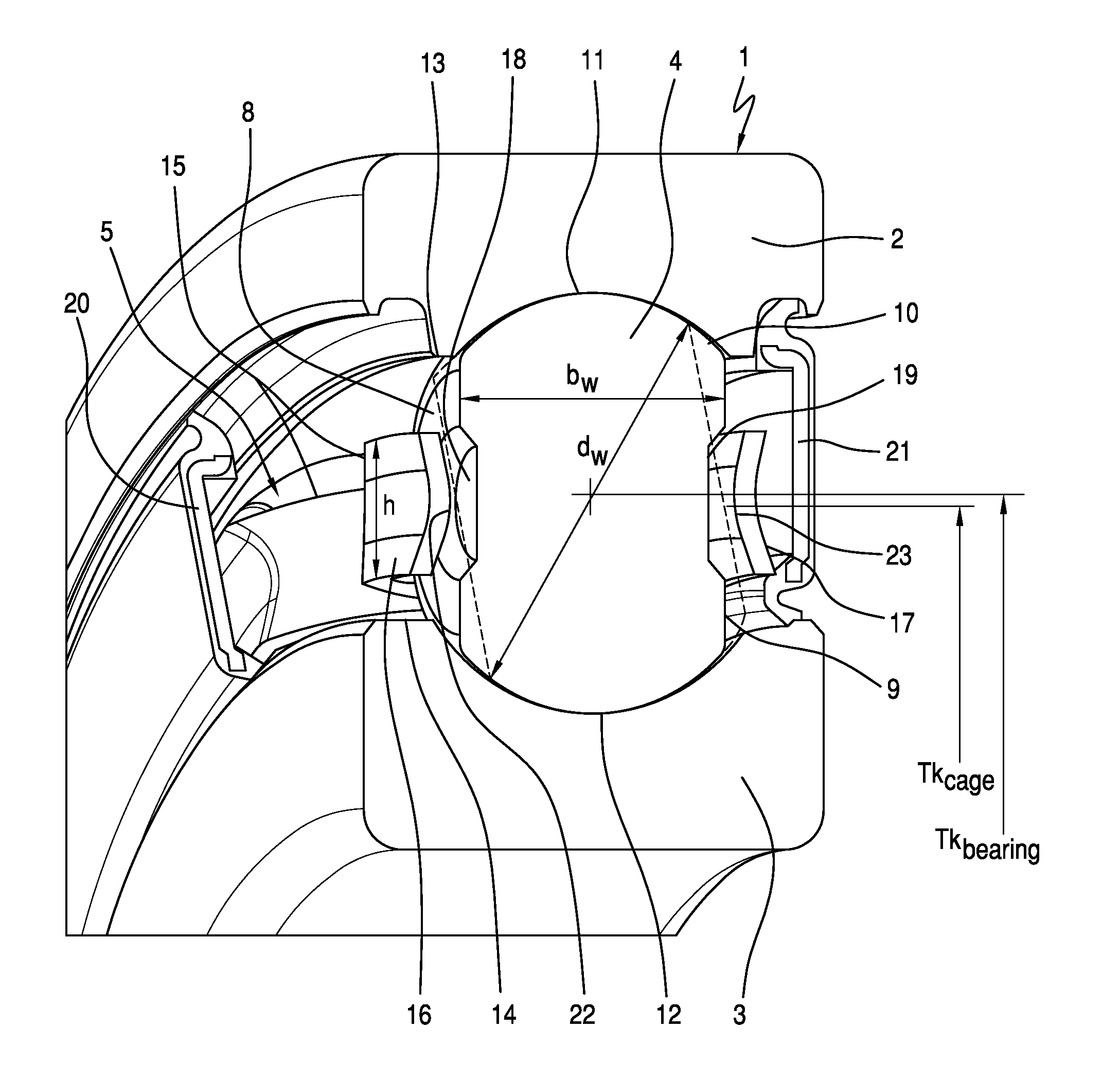
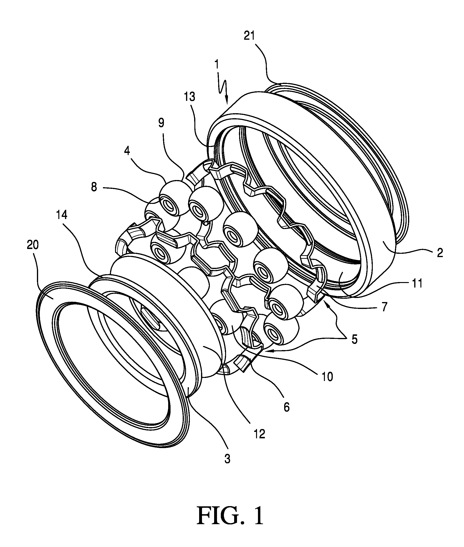
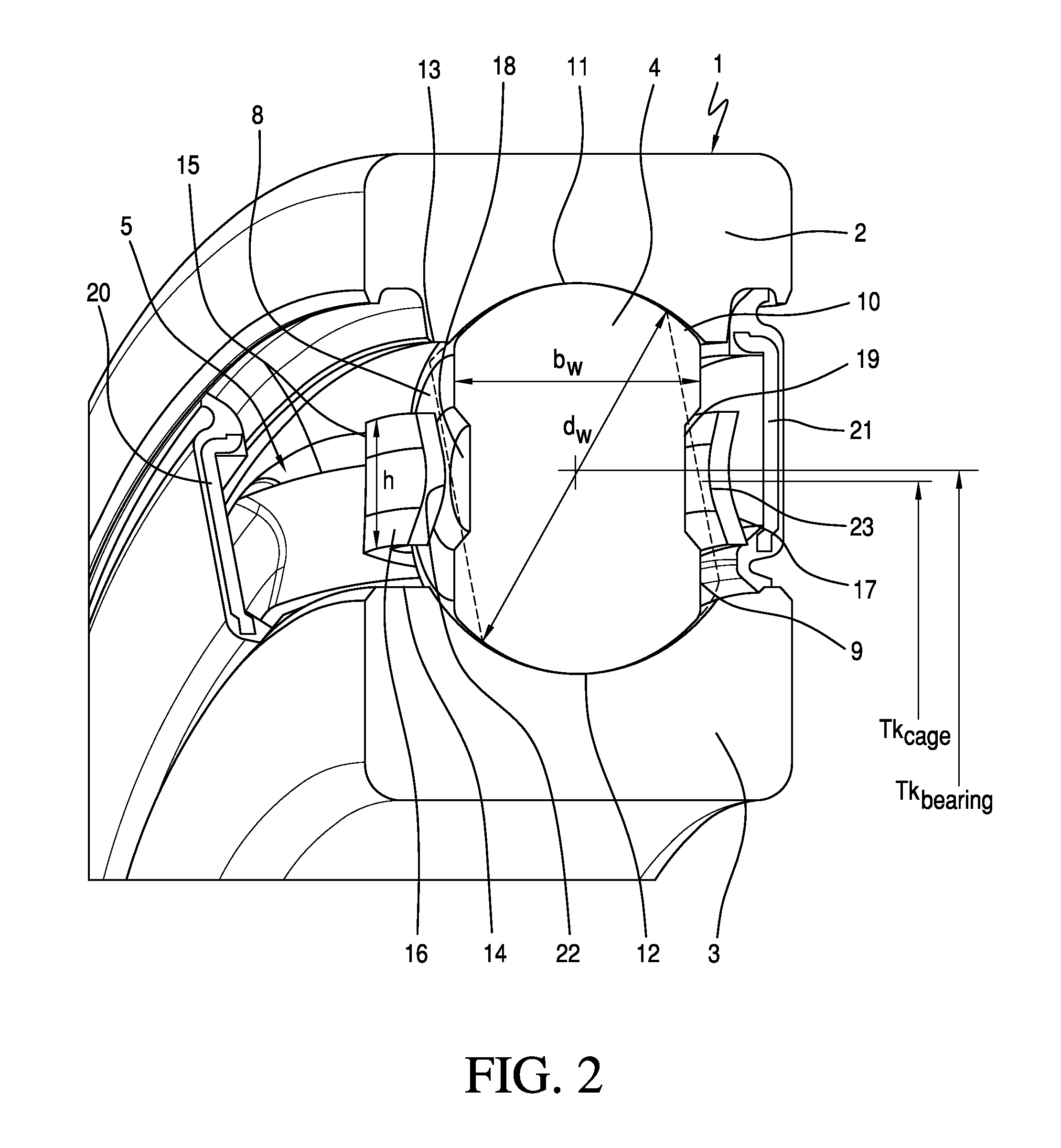
[0007]According to the invention, said object is achieved with a radial rolling bearing in that the bearing cage has individual cage pockets for each rolling body, which cage pockets surround said rolling bodies on a pitch circle line and in which the rolling bodies, by means of at least two low-friction lines of contact between their side surfaces and the longitudinal webs of the cage pockets, firstly have axial guidance between the bearing rings and secondly are formed with a defined degree of freedom for self-alignment to the pressure angle of the radial rolling bearing.

[0008]Preferred embodiments and advantageous refinements of the radial rolling bearing embodied according to the invention are described in the subclaims.

[0009]Preferably, central depressions are formed into the side surfaces of the rolling bodies, which provide an additional lubricant reservoir for the radial rolling bearing. Said central depressions are preferably formed in the manner of circular flat recesses, ...


PUM


Abstract

A radial rolling bearing, which has an outer bearing ring, an inner bearing ring, and rollers, which are arranged between the bearing rings and held at uniform distances from one another in a peripheral direction by a bearing cage in individual cage pockets. The rollers are spherical disks that have parallel lateral surfaces which are symmetrically flattened from a basic spherical shape and which roll in groove-type raceways with their faces. The raceways are incorporated into the inner face of the outer bearing ring and the outer face of the inner bearing ring. The rollers are axially guided between the bearing rings via two low-friction line contacts between lateral surfaces and the longitudinal webs of the cage pockets. The rollers are configured to have a defined degree of freedom for self-alignment to the pressure angle of the radial rolling bearing.

Description

FIELD OF THE INVENTION[0001]The invention relates to a radial rolling bearing which can be realized particularly advantageously in single-row deep groove ball bearings for mounting the main shaft in motor vehicle shift transmissions or for mounting tensioning rollers within the secondary drive of internal combustion engines.BACKGROUND OF THE INVENTION[0002]A person skilled in the art of rolling bearing technology is generally familiar with the fact that single-row deep groove ball bearings are rigid, non-dismantlable radial rolling bearings which are characterized primarily in that their radial and axial load capacity is equally high, and in that, on account of their low friction, they have the highest speed limits of all bearing types. Said deep groove ball bearings have been known for a long time and are composed substantially of an outer bearing ring and an inner bearing ring and of a number of balls, which are arranged between the bearing rings, as rolling bodies, which are guid...

Claims


Application Information

Patent Timeline
Patent Type & Authority Patents(United States)
IPC IPC(8): F16C33/36F16C33/46
CPCF16C19/26F16C33/36F16C33/4635F16C33/6614F16C33/547F16C33/565F16C33/4682F16C33/541Y02T10/86F16C33/54F16C35/06
Inventor HOFMANN, HEINRICHDOPPLING, HORSTBOHR, ANDREASEIDLOTH, RAINER
Owner SCHAEFFLER TECH AG & CO KG
Why Eureka
Try Eureka