Internal combustion engine exhaust gas purification apparatus and method for controlling same

a technology of exhaust gas purification apparatus and internal combustion engine, which is applied in the direction of arsenic compounds, separation processes, instruments, etc., can solve the problems of cyanic acid that has not been converted into ammonia leakage from the nox storage-reduction catalyst uni

Inactive Publication Date: 2011-02-22
TOYOTA JIDOSHA KK
View PDF15 Cites 37 Cited by
  • Summary
  • Abstract
  • Description
  • Claims
  • Application Information

AI Technical Summary

Benefits of technology

[0007]The invention provides an internal combustion engine exhaust gas purification apparatus that properly executes urea injection so as to suppress the production of cyanic acid unconvertible into ammonia and also provides a method for controlling such an internal combustion engine exhaust gas purification apparatus.
[0013]According to the internal combustion engine exhaust gas purification apparatus controlling method of the third aspect of the invention, as described above, the production of cyanic acid unconvertible into ammonia can be minimized, and thus leaks of cyanic acid from the NOx storage-reduction catalyst unit and / or the NOx selective reduction catalyst unit can be suppressed.
[0015]According to the internal combustion engine exhaust gas purification apparatus controlling method of the fourth aspect of the invention, as described above, the production of cyanic acid unconvertible into ammonia can be minimized, and thus leaks of cyanic acid from the NOx storage-reduction catalyst unit and / or the NOx selective reduction catalyst unit can be suppressed.

Problems solved by technology

Thus, if one or both of the catalyst temperatures is lower than the reference temperature, there is a possibility that the cyanic acid that has not been converted into ammonia leaks from the NOx storage-reduction catalyst unit and / or from the NOx selective reduction catalyst unit.

Method used


Image

  • Internal combustion engine exhaust gas purification apparatus and method for controlling same
  • Internal combustion engine exhaust gas purification apparatus and method for controlling same
  • Internal combustion engine exhaust gas purification apparatus and method for controlling same

Examples


Embodiment Construction

[0021]Hereinafter, example embodiments of the invention will be described with reference to the accompanying drawings.

[0022]First, the first example embodiment of the invention will be described.

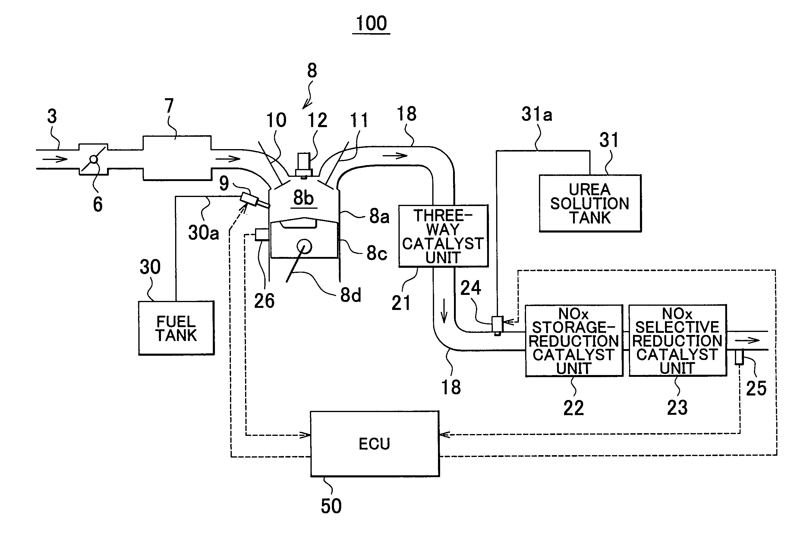
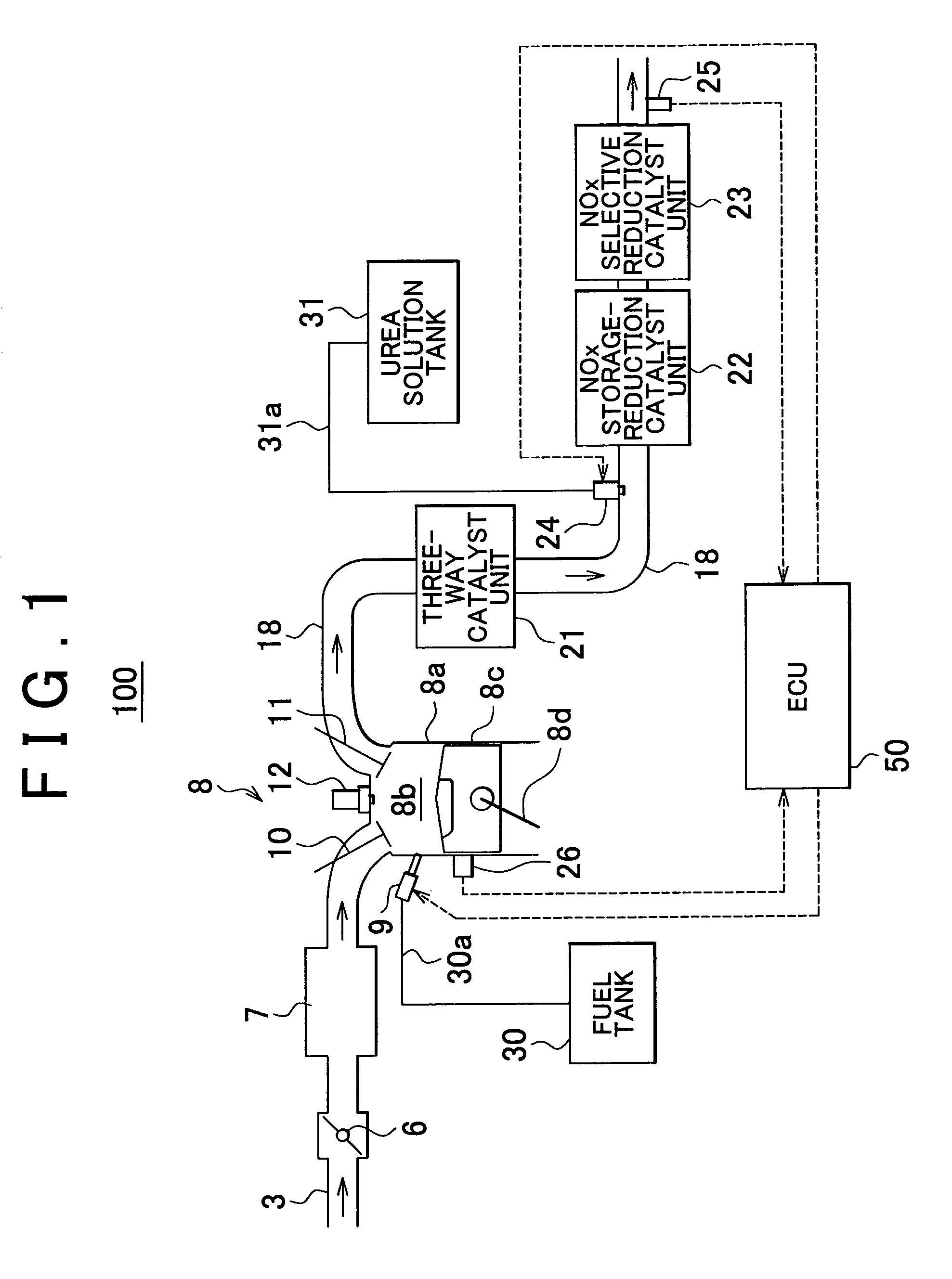
[0023]FIG. 1 schematically shows the configuration of a vehicle 100 incorporating an internal combustion engine exhaust gas purification apparatus according to the first example embodiment of the invention. In FIG. 1, the solid arrows represent gas flows, and the dotted arrows represent signal inputs and outputs.

[0024]The vehicle 100 has an intake air passage 3, a throttle valve 6, a surge tank 7, an engine (internal combustion engine) 8, a fuel injection valve 9, an exhaust gas passage 18, a three-way catalyst unit 21, a NOx storage-reduction catalyst unit 22, a NOx selective reduction catalyst unit 23, an urea injection valve 24, an exhaust gas temperature sensor 25, a fuel tank 30, an urea solution tank 31, and ECU (Electronic Control Unit) 50.

[0025]The intake air passage 3 is a passage t...


PUM


Abstract

An internal combustion engine exhaust gas purification apparatus purifies exhaust gas using a NOx storage-reduction catalyst unit and a NOx selective reduction catalyst unit. The NOx selective reduction catalyst unit is provided downstream of the NOx storage-reduction catalyst unit in an exhaust gas passage. An urea injecting mechanism, for example an injection valve, injects urea into the exhaust gas passage. An urea injection controller prohibits urea injection from the urea injecting mechanism if at least one of the temperatures of the NOx storage-reduction catalyst unit and the NOx selective reduction catalyst unit is equal to or lower than a reference temperature. As such, production of cyanic acid is minimized, and therefore leaks of cyanic acid from the NOx storage-reduction catalyst unit and / or the NOx selective reduction catalyst unit can be suppressed.

Description

BACKGROUND OF THE INVENTION[0001]1. Field of the Invention[0002]The invention relates to an internal combustion engine exhaust gas purification apparatus and a method for controlling the same apparatus.[0003]2. Description of the Related Art[0004]Exhaust gas purification apparatuses have been proposed which incorporate a high-temperature activation NOx catalyst unit and a low-temperature activation NOx catalyst unit both provided in an exhaust gas passage to remove NOx. For example, Japanese Patent Application Publication No. 2004-218475 (JP-A-2004-218475) describes an exhaust gas purification apparatus in which a NOx selective reduction catalyst unit is provided upstream of a NOx storage-reduction catalyst unit and urea is injected into the exhaust gas passage. Thus configured, this exhaust gas purification apparatus is capable of removing NOx both at a low temperature and at a high temperature. More specifically, in the exhaust gas purification apparatus described in this publicat...

Claims


Application Information

Patent Timeline
Patent Type & Authority Patents(United States)
IPC IPC(8): B01D53/56B01D53/94F01N3/10
CPCF01N3/0814F01N3/208F01N2560/021F01N2560/06F01N2610/02F01N2610/146F01N2900/08Y10S423/06Y10S423/05Y02T10/24Y02T10/12
Inventor KATOH, KENJI
Owner TOYOTA JIDOSHA KK
Why Eureka
Try Eureka