

Imaging lens
a technology of imaging lens and lens body, applied in the field of imaging lens, can solve the problems of difficult compacting imaging lens, difficult optical length, difficult back focus ratio, etc., and achieve the effect of not reducing compactness, good images, and good image quality
- Summary
- Abstract
- Description
- Claims
- Application Information
AI Technical Summary
Benefits of technology
Problems solved by technology
Method used
Image

Examples
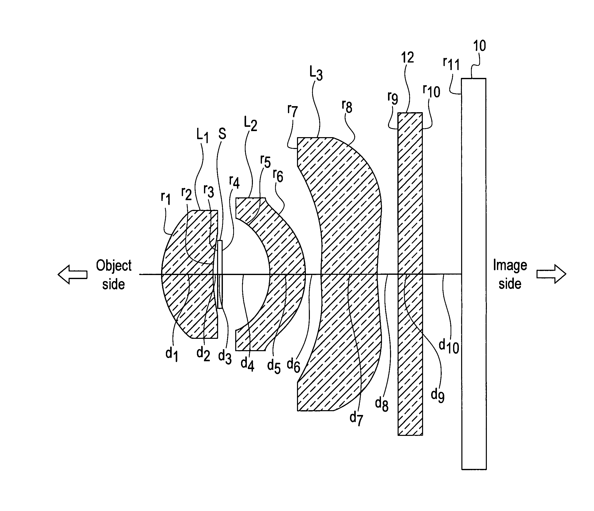
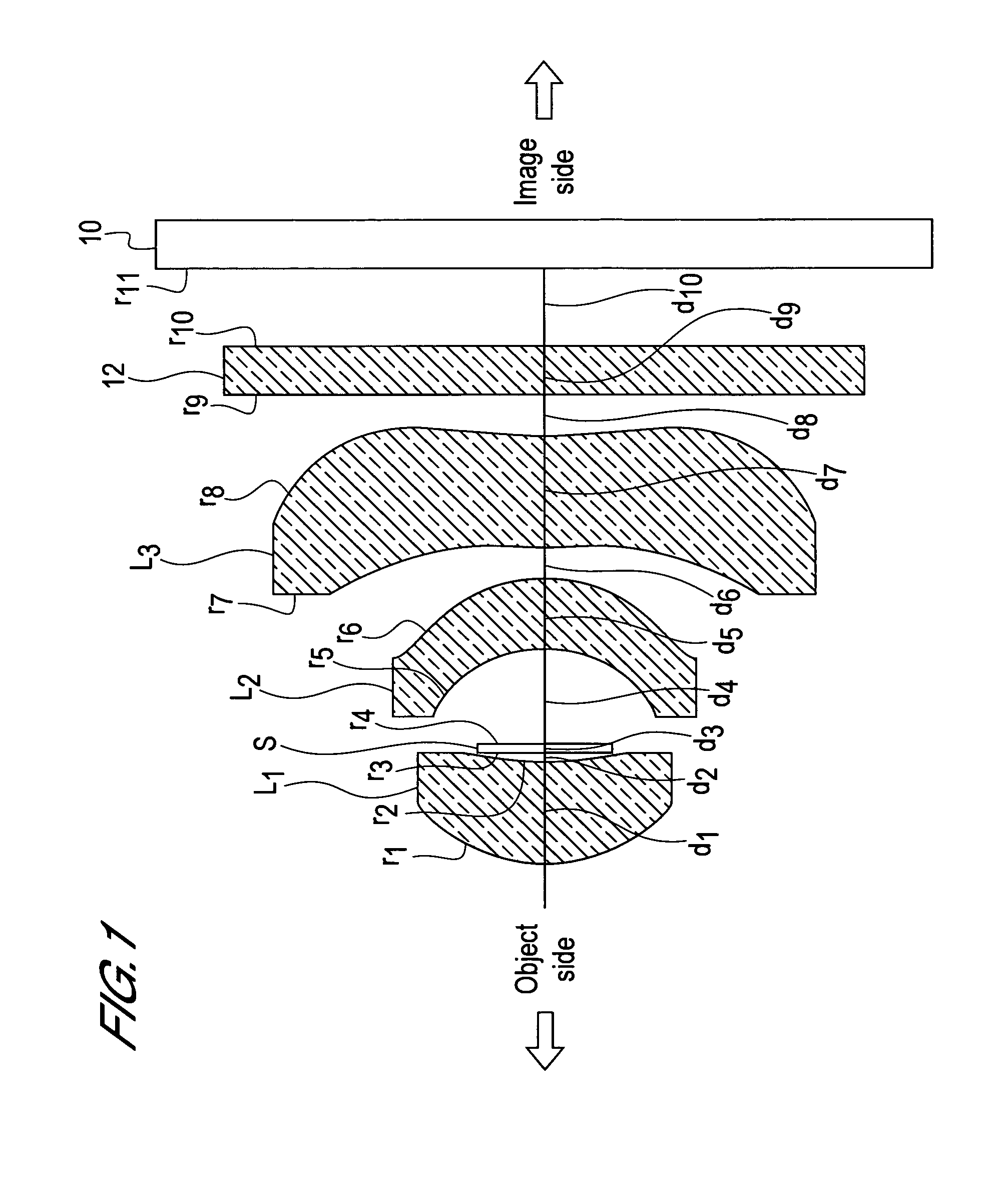
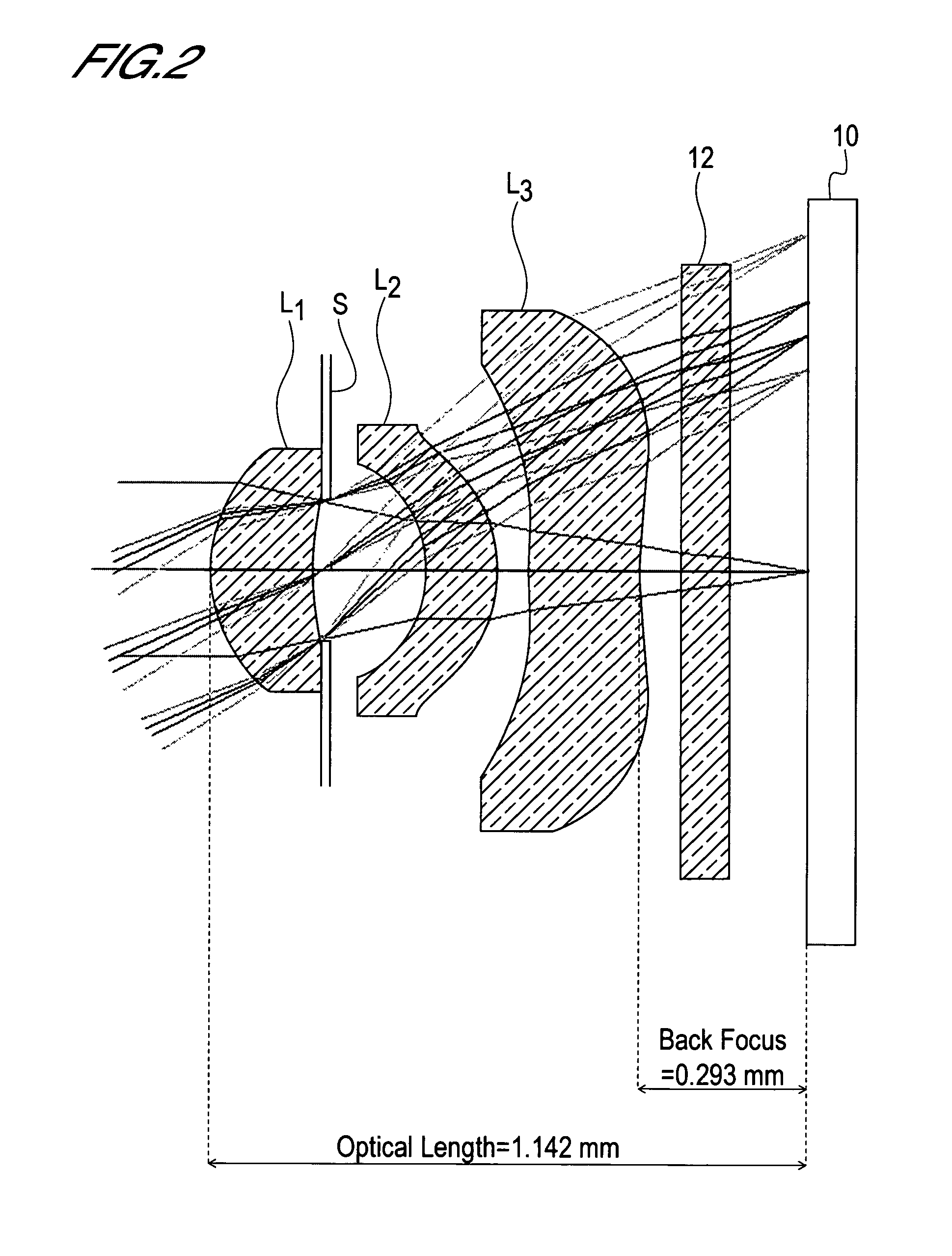
first embodiment
(A) The optical length D is D=1.142 mm as shown in FIG. 2.
(B) The radius of curvature r1 in the vicinity of the optical axis on the object side face of the first lens L1 is r1=0.316 mm as shown in Table 1.
(C) The focal length f1 of the first lens L1 is f1=0.89 mm as shown in Table 1.
(D) The focal length f3 of the third lens L3 is f3=−3.28 mm as shown in Table 1.
(E) The Abbe number ν of the second lens L2 is ν (=ν5)=56.0 as shown in Table 1 (the Abbe number ν of the second lens L2 is denoted as ν5 in Table 1).
Therefore
D / f=1.142 / 1.00=1.142 (1)
r1 / f=0.316 / 1.00=0.316 (2)
f1 / f=0.89 / 1.00=0.89 (3)
f3 / f=−3.28 / 1.00=−3.28 (4)
ν(=ν5)=56.0 (5)
So the lens system in the first embodiment satisfies the following Conditional Expressions (1) to (5).
0.90<D / f<1.20 (1)
0.20<r1 / f<0.35 (2)
0.80<f1 / f<1.00 (3)
−9.00<f3 / f<−3.20 (4)
50.0<ν<60.0 (5)
As FIG. 2 and Table 1 shows, the aperture stop S is disposed at a position behind the second surface (surface at the image side) of the fi...
second embodiment
(A) The optical length D is D=1.108 mm as shown in FIG. 6.
(B) The radius of curvature r1 in the vicinity of the optical axis on the object side face of the first lens L1 is r1=0.283 mm as shown in Table 2.
(C) The focal length f1 of the first lens L1 is f1=0.82 mm as shown in Table 2.
(D) The focal length f3 of the third lens L3 is f3=−8.62 mm as shown in Table 2.
(E) The Abbe number ν of the second lens L2 is ν (=ν5)=56.4 as shown in Table 2 (the Abbe number ν of the second lens L2 is denoted as ν5).
Therefore
D / f=1.108 / 1.00=1.108 (1)
r1 / f=0.283 / 1.00=0.283 (2)
f1 / f=0.82 / 1.00=0.82 (3)
f3 / f=−8.62 / 1.00=−8.62 (4)
ν(=ν5)=56.4 (5)
So the lens system in the second embodiment satisfies the following Conditional Expressions (1) to (5).
0.90<D / f<1.20 (1)
0.20<r1 / f<0.35 (2)
0.80<f1 / f<1.00 (3)
−9.00<f3 / f<−3.20 (4)
50.0<ν<60.0 (5)
[0150]As FIG. 6 and Table 2 shows, the aperture stop S is disposed at a position behind the second surface (surface at the image side) of the first ...
PUM
| Property | Measurement | Unit |
|---|---|---|
| Abbe number | aaaaa | aaaaa |
| Abbe number | aaaaa | aaaaa |
| Abbe number | aaaaa | aaaaa |
Abstract
Description
Claims
Application Information