Object information acquiring apparatus and control method thereof, and acoustic signal acquiring apparatus and control method thereof

a technology of object information and control method, which is applied in the field of object information acquisition apparatus and control method thereof, and the acquisition of acoustic signal apparatus, which can solve the problems of “rolling shutter distortion, deviating from the received signal, and reducing the burden on the tes

Inactive Publication Date: 2016-05-19
CANON KK
View PDF55 Cites 5 Cited by
  • Summary
  • Abstract
  • Description
  • Claims
  • Application Information

AI Technical Summary

Benefits of technology

[0038]According to this invention, good images can be acquired in an acoustic signal acquiring apparatus that sequentially acquires signals for each element group.
[0039]Further features of the present invention will become apparent from the following description of exemplary embodiments with reference to the attached drawings.

Problems solved by technology

If the object is an organism, acquiring and imaging acoustic signals in a short time, particularly at a medical site, decreases burden on the testee.
However, in the case of the rolling shutter method that sequentially acquires data for each part of arrayed element groups, a signal to be received deviates depending on the element group, since the data acquisition time deviates depending on the element group.
This problem is known as “rolling shutter distortion” in a rolling shutter type CMOS sensor, which is used in a video camera.

Method used


Image

  • Object information acquiring apparatus and control method thereof, and acoustic signal acquiring apparatus and control method thereof
  • Object information acquiring apparatus and control method thereof, and acoustic signal acquiring apparatus and control method thereof
  • Object information acquiring apparatus and control method thereof, and acoustic signal acquiring apparatus and control method thereof

Examples


embodiment 1

Configuration

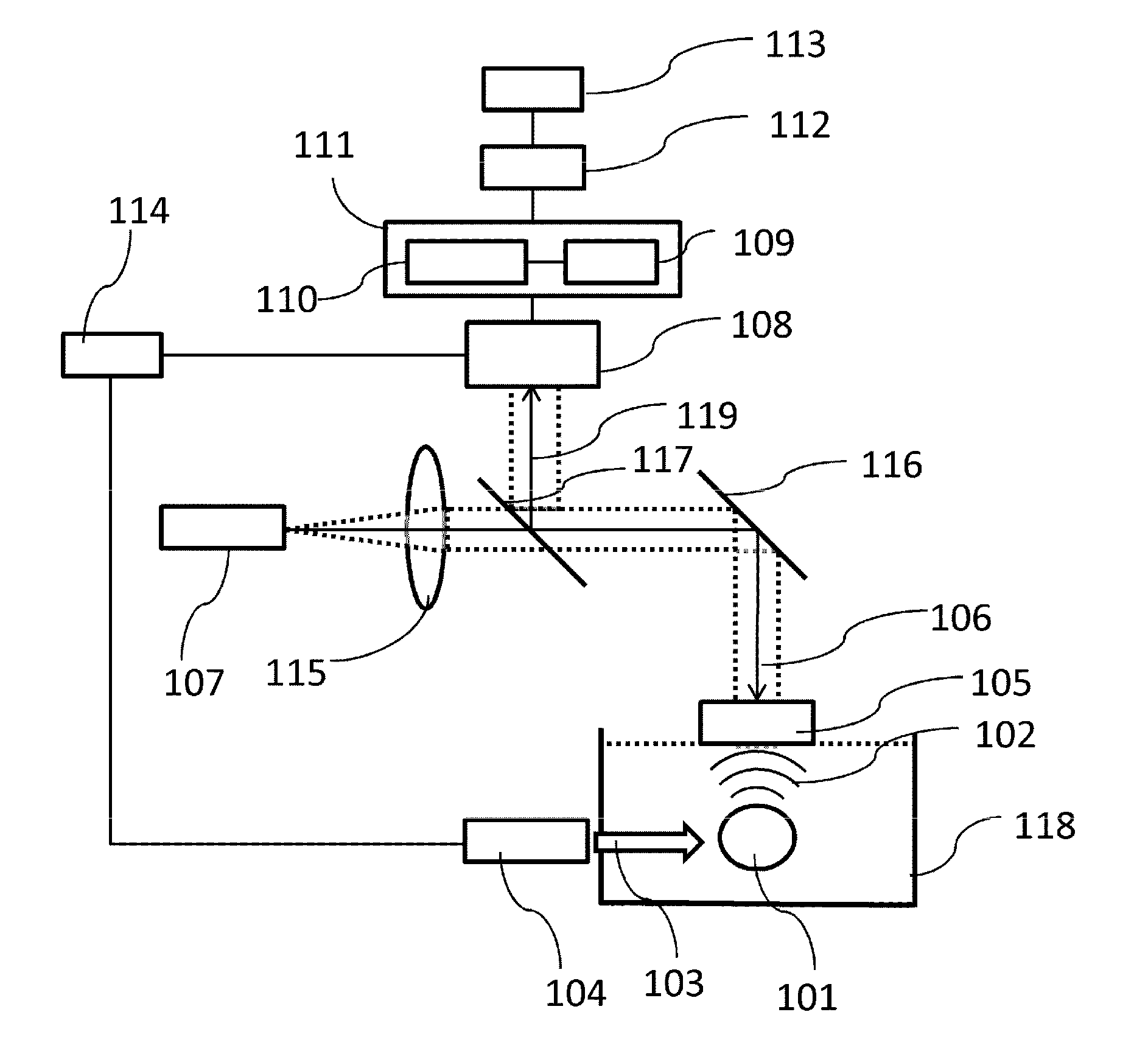
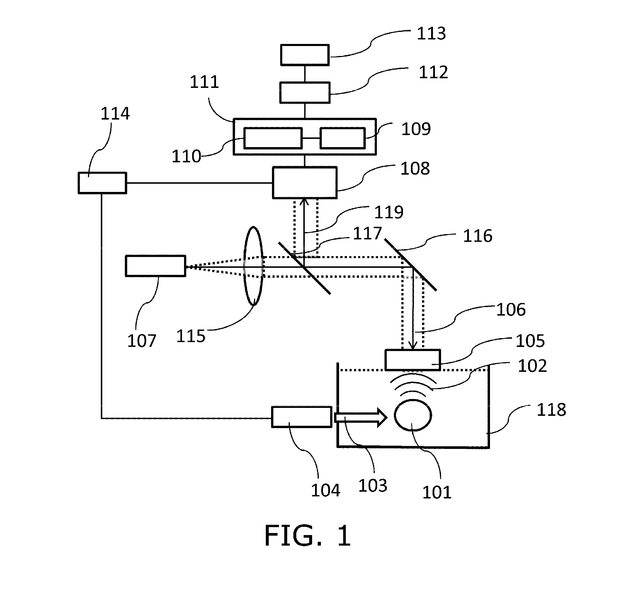
[0062]First an overview of a configuration of an imaging apparatus according to this embodiment will be described with reference to FIG. 1. The imaging apparatus of this embodiment includes an excitation light source 104 that emits excitation light 103. The excitation light 103 is irradiated onto an object 101. If the object 101 is an organism, light absorbers inside the object 101, such as a tumor and blood vessel, and light absorbers on the surface of the object 101, can be imaged. If these light absorbers absorb a part of the energy of the excitation light 103, a photoacoustic wave 102 is generated, which propagates in the object. The object 101 is placed in a water tank 118 which is filled with water.

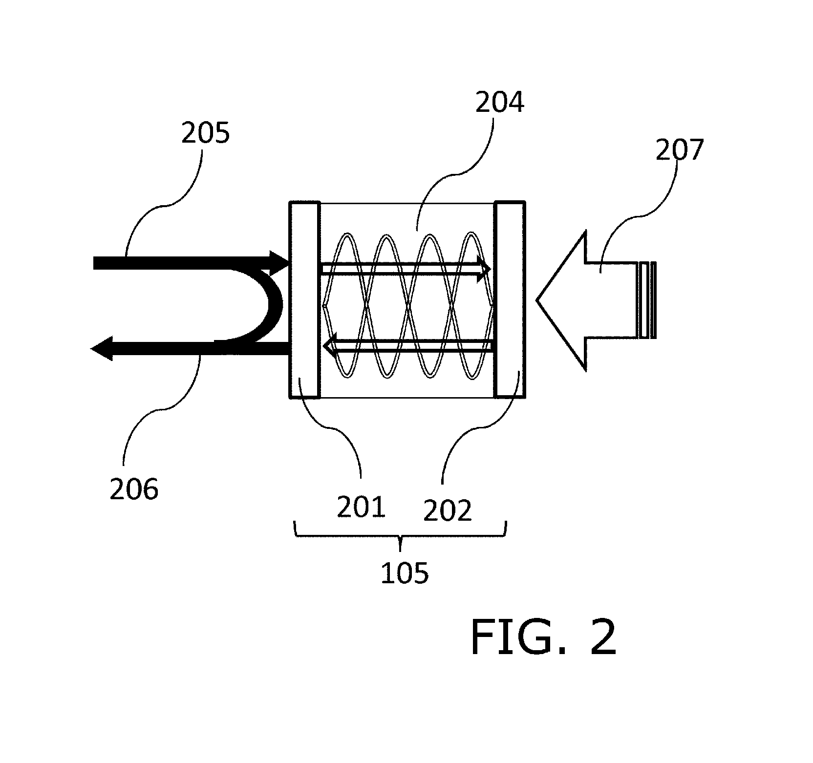
[0063]The imaging apparatus generates a measurement light 106 by a light source for measurement light 107, and irradiates the measurement light 106 onto a Fabry-Perot probe 105, so as to detect a sound pressure of the photoacoustic wave 102. In concrete terms, the quant...

embodiment 2

[0123]FIG. 12 is a diagram depicting a configuration example of the imaging apparatus of this embodiment. The imaging apparatus of this embodiment images an acoustic impedance distribution in the object. Description on the composing elements the same as Embodiment 1 is omitted.

[0124]The imaging apparatus of this embodiment includes a transducer 1204 that generates an elastic wave 1202 and transmits it to an object 1201, and a pulser 1205 that allows the transducer 1204 to generate the elastic wave, instead of the excitation light generation apparatus.

[0125]The imaging apparatus also includes a Fabry-Perot probe 1206 that detects an elastic wave, which was reflected on a surface of a tissue having different acoustic impedance, such as a tumor, in the object 1201, and which propagated through the object. Configurations and functions of an array type photosensor 1208 (in this case a CMOS sensor) which uses the rolling shutter method, a light source for measurement light 1212 that irrad...

embodiment 3

[0130]Just like Embodiment 1, an imaging apparatus of this embodiment detects a photoacoustic wave generated from an object by the irradiation of light, and image optical characteristic value distribution information in an organism.

[0131]FIG. 13 shows a configuration example of the imaging apparatus of this embodiment. A major difference of this embodiment from Embodiment 1 is that an array type transducer 1301 utilizing piezoelectric phenomena or a change in capacitance is included as means for detecting the photoacoustic wave 102, instead of the Fabry-Perot probe 105 or the array type photosensor 108. This means that this embodiment does not include the light source for measurement light and the optical system to guide the measurement light and the reflected light.

[0132]A control unit 1306 of this embodiment controls the signal acquisition and the output of the transducer 1301 and the light emitting timing of an excitation light source 1305. This embodiment also includes a correct...


PUM


Abstract

Provided is an object information acquiring apparatus having: a receiver in which a plurality of receiving elements to receive acoustic signals based on an acoustic wave propagated from an object is disposed on a two-dimensional surface, the plurality of receiving elements being divided into a plurality of receiving element groups including at least one receiving element respectively; a corrector that corrects signals received by the receiver; and a processor that acquires characteristic information in the object using the signals corrected by the corrector, wherein the receiver receives the acoustic signals for each of the plurality of receiving element groups with a time difference, and acquires the received signals, and the corrector corrects a time-based deviation.

Description

TECHNICAL FIELD[0001]The present invention relates to an object information acquiring apparatus and a control method thereof, and an acoustic signal acquiring apparatus and a control method thereof.BACKGROUND ART[0002]Recently many imaging apparatuses that use X-rays, ultrasound and MRI (nuclear Magnetic Resource Imaging methods) are used in medical fields. On the other hand, research in optical imaging apparatuses that acquire information in an organism (object) by propagating light irradiated from a light source, such as laser, through the object and detecting the propagated light or the like, have also been vigorously ongoing in the medical fields. As one such optical imaging technique, photoacoustic tomography (PAT) has been proposed.[0003]In PAT, a pulsed light generated in the light source is irradiated onto an object, and an acoustic wave, generated from biological tissue that absorbed the energy of light propagated and diffused inside the object (hereafter called “photoacous...

Claims


Application Information

Patent Timeline
Patent Type & Authority Applications(United States)
IPC IPC(8): G01S7/52G01S7/56
CPCG01S7/56G01S7/52004A61B5/0095A61B2562/0204A61B2562/0247A61B2562/0266A61B2562/043G01H3/00G01H9/00
Inventor IMAI, TORUASAO, YASUFUMINAKAJIMA, TAKAO
Owner CANON KK
Why Eureka
Try Eureka