
Method including a radio transmitter for improving radio link operation

a radio transmitter and radio link technology, applied in the direction of transmission monitoring, instruments, polarisation/directional diversity, etc., can solve the problems of affecting affecting the operation of main beams, and affecting the operation of other antenna sectors, so as to reduce improve the operation of downlinks, and reduce interference. the effect of the level of side beams

Inactive Publication Date: 2011-02-22
RPX CORP
View PDF15 Cites 0 Cited by
  • Summary
  • Abstract
  • Description
  • Claims
  • Application Information

AI Technical Summary

Benefits of technology

[0016]The method and arrangement of the invention provide several advantages. The traditional beamforming methods, which employ balanced weighting of signals of different antenna elements, provide a radiation pattern which has the narrowest possible main antenna beam. Such a radiation pattern is ideal for the AWGN channel. However, in several radio systems the angular spread of the signal received from the uplink is often greater than the width of the main beam of the transmitting antenna in the downlink, which results in poor operation of the downlink. By shaping the main beam it is possible to compensate for the antenna's directional inaccuracy, i.e. the fact that the desired receiver cannot be located accurately, which can happen in the case of a mobile receiver, for example. A receiver located at the edge of an antenna sector can also be reached better by shaping the radiation pattern. In addition, reduction of the level of side beams decreases the interference caused to the other antenna sectors of the same system and to other systems. Shaping of the main beam and reduction of the level of side beams also allow to decrease the transmission power, which increases the dynamics of transmission power. Furthermore, less transmission power is wasted on the side beams.

Problems solved by technology

A disadvantage of the method described above is that it is impossible to influence the level of side beams and thus the interference caused to other antenna sectors.
Furthermore, the extent to which the main beam can be modified is relatively limited.

Method used


Image

  • Method including a radio transmitter for improving radio link operation
  • Method including a radio transmitter for improving radio link operation
  • Method including a radio transmitter for improving radio link operation

Examples


Embodiment Construction

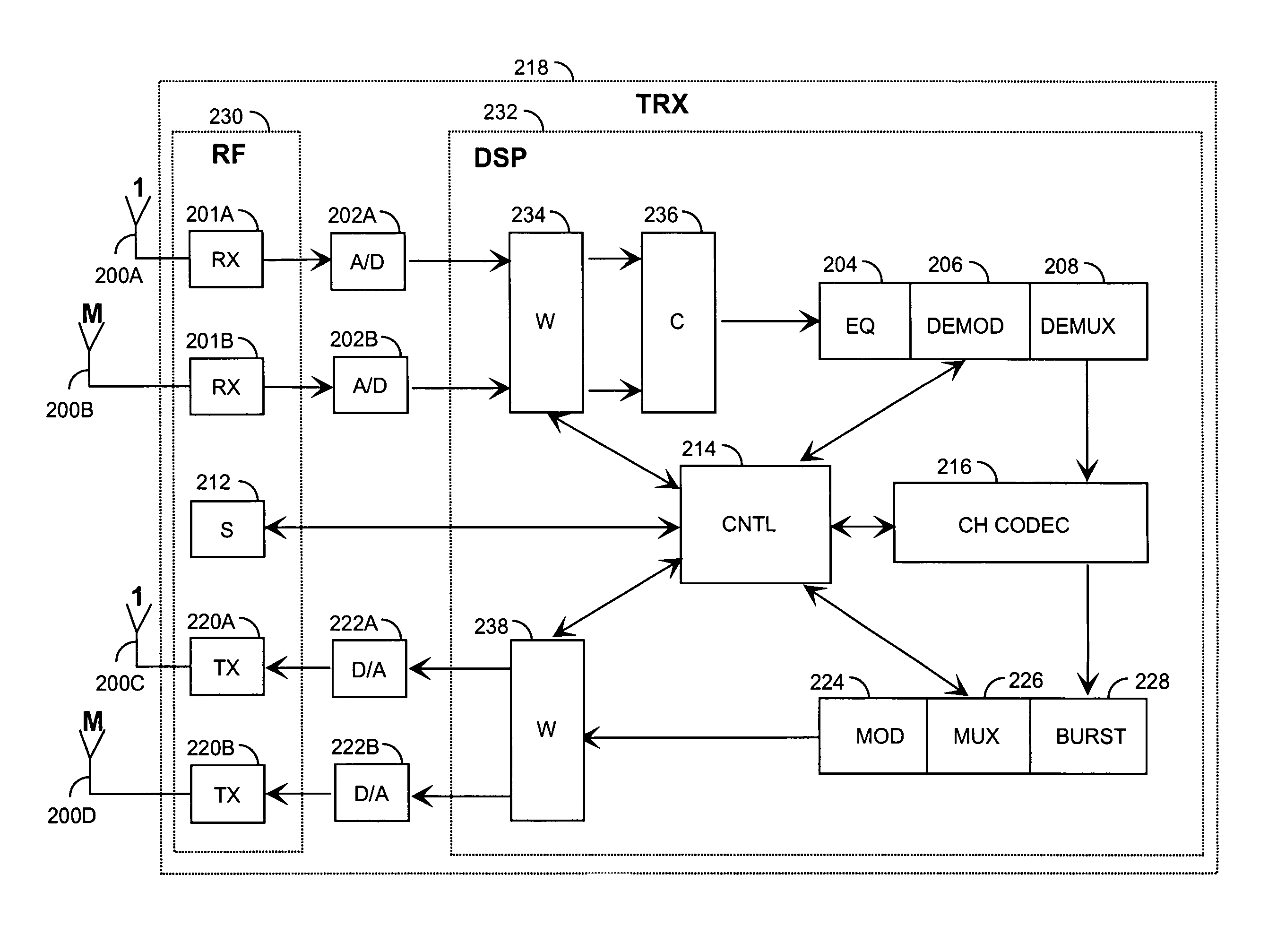
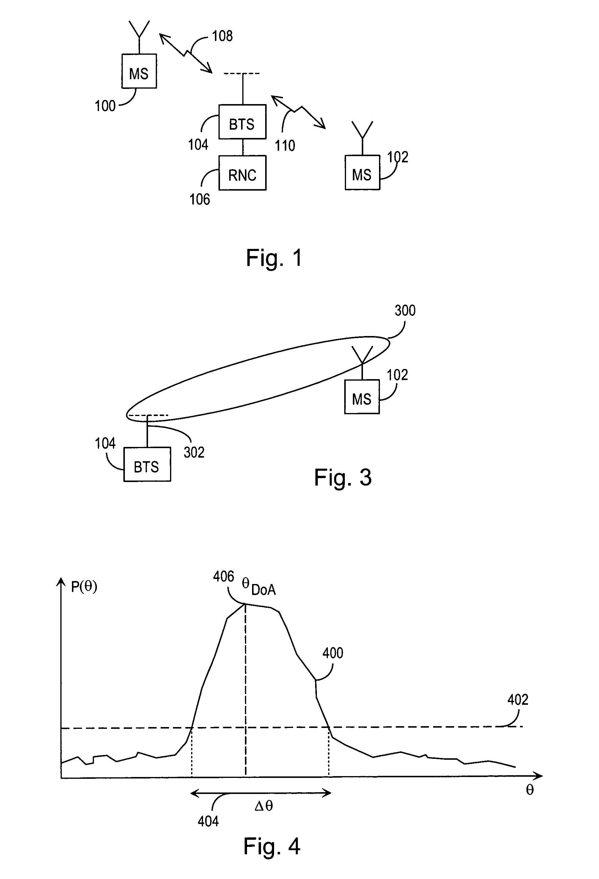
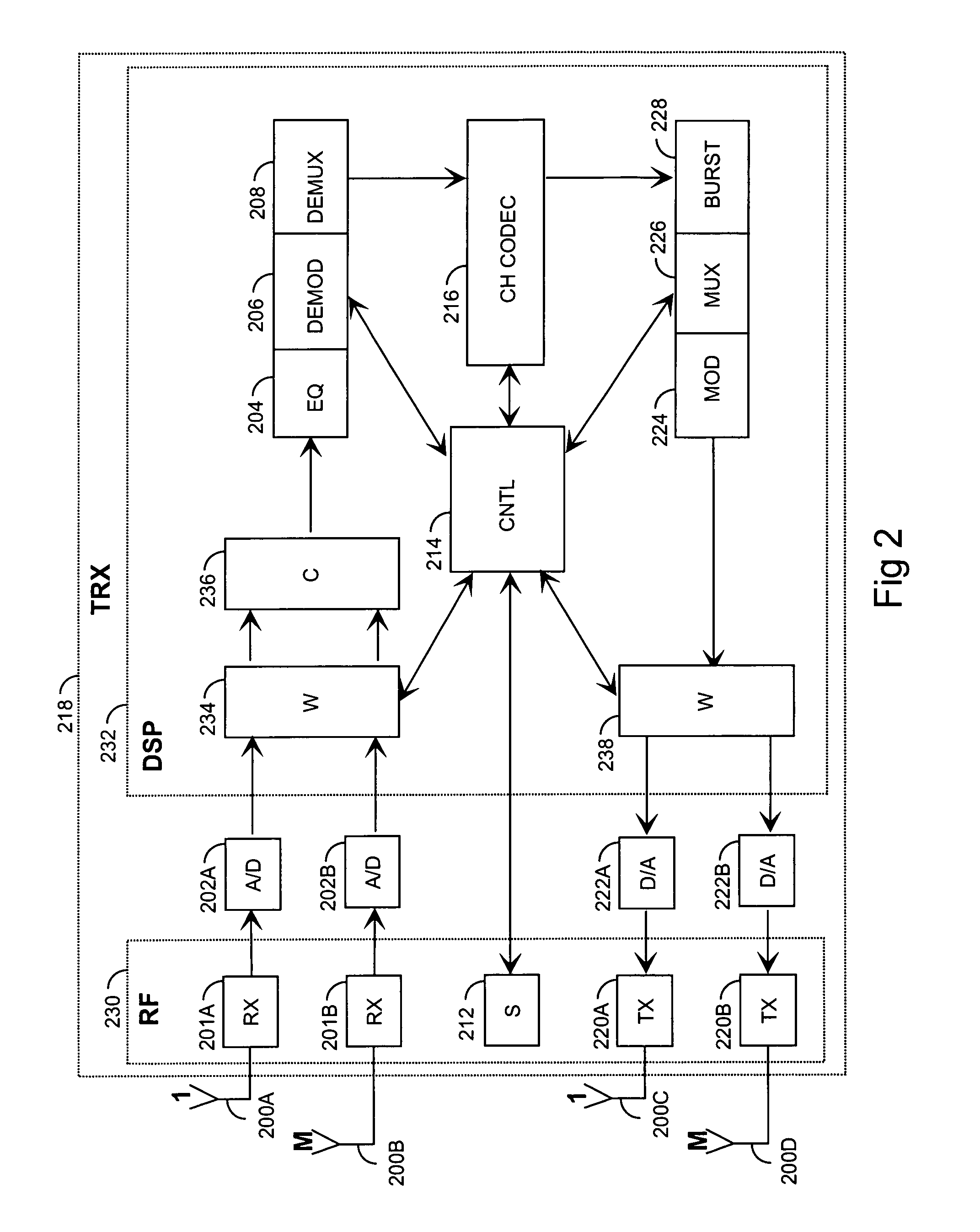
[0026]The present invention can be applied in various wireless communication systems, such as cellular radio systems. It is irrelevant which multiple access method is used. For example, the CDMA (Code Division Multiple Access), the WDCMA (Wideband Code Division Multiple Access) and the TDMA (Time Division Multiple Access) or their hybrids can be used. It is also clear to a person skilled in the art that the method according to the invention can be applied to systems utilizing different modulation methods or air interface standards. FIG. 1 is a simplified illustration of a digital data transmission system to which the solution according to the invention is applicable. This is part of a cellular radio system, which comprises a base station 104, which has a bi-directional radio link 108 and 110 to subscriber terminals 100 and 102. The subscriber terminals may be fixed, placed in a vehicle or portable. The base station includes transmitters, for instance. From the transceivers of the ba...


PUM


Abstract

The invention relates to a method and a system for improving operation of a radio link in a wireless communication system, such as a cellular radio system, by modifying the radiation pattern of an antenna array on the downlink by means of the information obtained from the uplink. The method comprises determining the location of a receiver for transmission by means of an angular power spectrum (400), for example. Then the radiation pattern of a transmitting antenna array is shaped on the basis of the location information on the receiver by selecting a window function which provides the desired radiation pattern and by implementing the form of the window function by means of antenna element specific coefficients (502, 504).

Description

[0001]This application is a continuation of international application PCT / FI01 / 00201 filed Feb. 28, 2001, which designated the US and was published under PCT article 21(2) in EnglishFIELD OF THE INVENTION[0002]The invention relates to a method and a system for improving operation of a radio link in a wireless communication system, such as a cellular radio system.BACKGROUND OF THE INVENTION[0003]As the number of users of wireless communication systems, such as cellular radio systems, increases and fast data transmission becomes more common in these systems, it is vitally important to increase the capacity of the systems by improving their performance. One way to solve this problem is to use one or more adaptive antenna arrays instead of sector antennas. In an antenna array individual antenna elements are typically located close to one another, i.e. at a distance corresponding to about half a wavelength. Such arrays typically comprise as many antennas as are needed to achieve the desi...

Claims


Application Information

Patent Timeline
Patent Type & Authority Patents(United States)
IPC IPC(8): H04M1/00H04B1/00H01Q3/26H04B7/06H04B7/10H04B7/26
CPCH04B7/0615
Inventor YLITALO, JUHA
Owner RPX CORP
Features
  • Generate Ideas
  • Intellectual Property
  • Life Sciences
  • Materials
  • Tech Scout
  • Unparalleled Data Quality
  • Higher Quality Content
  • 60% Fewer Hallucinations
Learn More