Method of molding a resin coated bearing, method of manufacturing a resin coated bearing, and a resin coated bearing molded by the molding method

a technology of resin coating bearing and molding method, which is applied in the direction of manufacturing tools, other domestic objects, mechanical instruments, etc., can solve the problems of unstable cutting face of film gate and achieve the effect of uniform strength and easy generation of burr

Active Publication Date: 2011-03-01
DAIDO METAL CO LTD +1
View PDF3 Cites 3 Cited by
  • Summary
  • Abstract
  • Description
  • Claims
  • Application Information

AI Technical Summary

Benefits of technology

[0005]However, insert-molding with the film gate system shown in JP-A-08-142112 involves a disadvantage that since a dummy shaft is arranged in a cavity, there is a need of removing a runner together with the dummy shaft when the runner is to be removed in an after treatment after molding, so the after treatment is troublesome and the presence of the dummy shaft makes a cut face of a film gate unstable with the result that burr is easily generated. The invention has been thought of in view of the situation and has its object to provide a method of molding a resin coated bearing, in which method a coating resin is made uniform in strength by eliminating a weld portion at the time if insert-molding and generation of burr can be suppressed at the time of after treatment after molding, a method of manufacturing a resin coated bearing, and a resin coated bearing molded by the molding method.
[0018]With regard to the first aspect of the invention, since a molten resin is filled into the cavity through the whole circular film gate, so that any weld is absent on the coating member, which is made of a synthetic resin and covers an outer race, thus enabling uniformizing the coating member in resin strength and suppressing generation of crack on the coating member also at the time of high loading. Also, since the film gate formed at a whole peripheral edge of the disk space is formed from the first die and the second die, there is an advantage that after working suffices to take out a resin coated bearing from the both dies and to cut a runner in the disk space.
[0020]With regard to the third aspect of the invention, since adherence of the coating member to the outer race can be heightened by the plurality of coming-off preventive recesses formed on the outer peripheral surface of the outer race and the round-shaped projection between the coming-off preventive recesses and an applied load stress can be dispersed by the round-shaped projection, the coming-off preventing function of the coating member can be considerably heightened as a whole. Also, the projection formed on the other end side of the outer peripheral surface of the outer race makes it possible to cut the runner filled in the disk space at the film gate in a manner to eliminate generation of burr.
[0022]With regard to the second embodiment of the invention, since the coating member is made of a fiber reinforced synthetic resin, which is obtained by mixing a main component of nylon having a high softening temperature with carbon fibers, it is possible to restrict elongation of the coating member whereby it is possible to further surely prevent the coating member from coming off the outer race.
[0023]With regard to the third embodiment of the invention, it is possible to maintain smooth opening and closing of a sliding door over a long term when the resin coated bearing is used for a guide roller of a vehicular sliding door.

Problems solved by technology

However, insert-molding with the film gate system shown in JP-A-08-142112 involves a disadvantage that since a dummy shaft is arranged in a cavity, there is a need of removing a runner together with the dummy shaft when the runner is to be removed in an after treatment after molding, so the after treatment is troublesome and the presence of the dummy shaft makes a cut face of a film gate unstable with the result that burr is easily generated.

Method used


Image

  • Method of molding a resin coated bearing, method of manufacturing a resin coated bearing, and a resin coated bearing molded by the molding method
  • Method of molding a resin coated bearing, method of manufacturing a resin coated bearing, and a resin coated bearing molded by the molding method
  • Method of molding a resin coated bearing, method of manufacturing a resin coated bearing, and a resin coated bearing molded by the molding method

Examples


Embodiment Construction

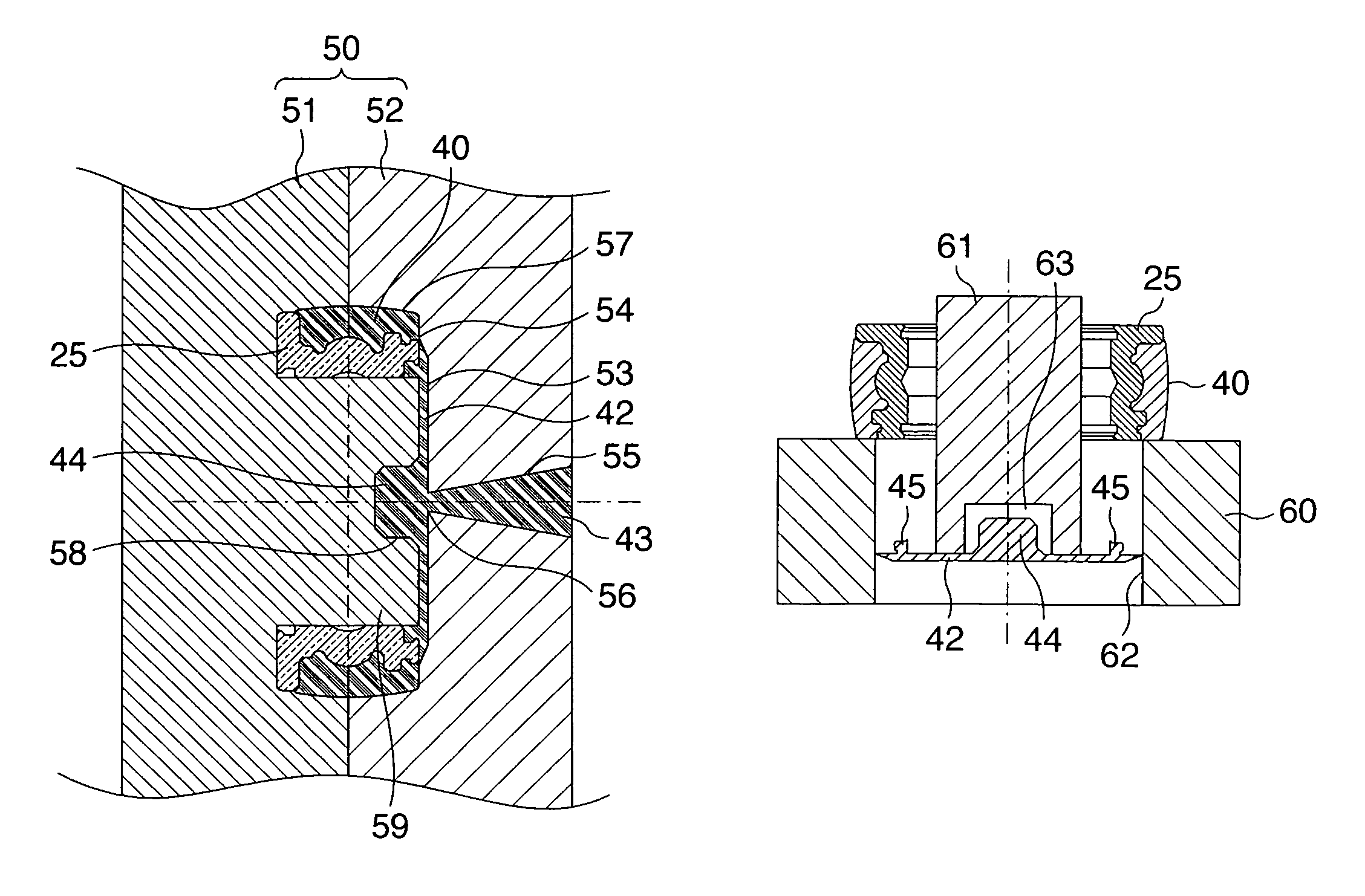
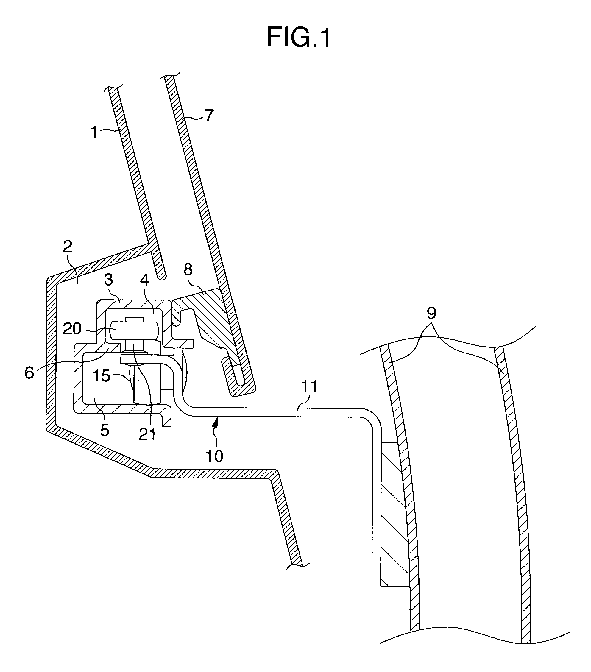
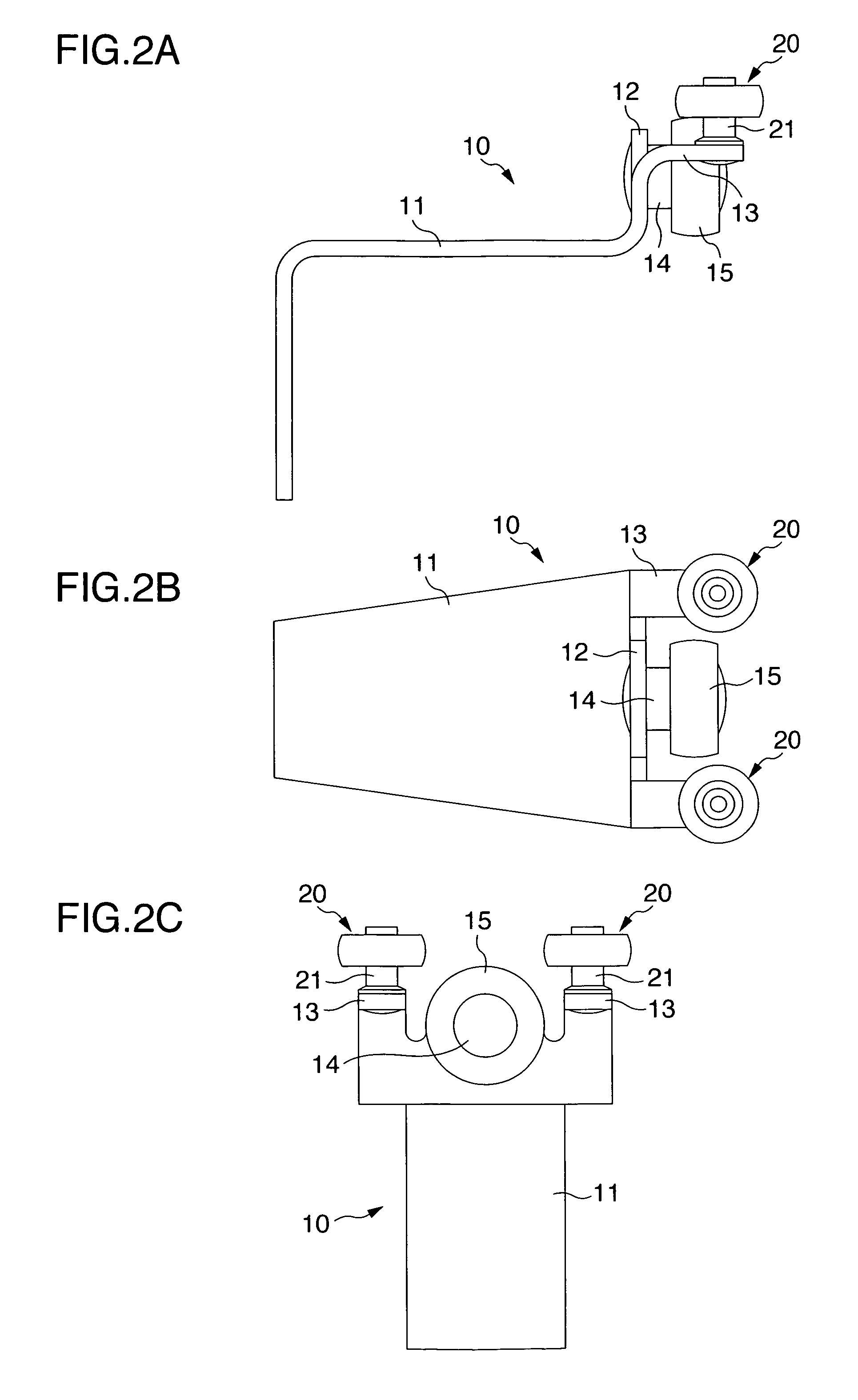
[0032]Referring to FIGS. 1 to 3, an explanation will be provided below to an embodiment of a resin coated bearing for vehicular sliding doors, to which resin coated bearings 20 according to the invention are applied. FIG. 1 is a cross sectional view showing a center rail part, to which the resin coated bearings 20 according to the embodiment are applied, FIGS. 2A, 2B and 2C are a front view, a plan view, and a right side view showing the outline of a center guide roller mechanism 10, to which the resin coated bearings 20 are applied, and FIG. 3 is a partially fragmentary, front view showing an internal structure of the resin coated bearing 20.

[0033]With a vehicular sliding door, as described above, an upper guide roller provided on an upper portion of a front end of a sliding door, a center guide roller provided centrally of a rear end in a heightwise direction, and a lower guide roller provided on a lower portion of the front end are caused to engage rollingly with an upper rail pr...


PUM

PropertyMeasurementUnit
heightaaaaaaaaaa
depthaaaaaaaaaa
strengthaaaaaaaaaa

Abstract

Disclosed is a method of molding a resin coated bearing. When a molten resin is injected toward a substantially central portion of a disk space of forming dies from a sprue formed on an upper die, the molten resin is filled into a cavity through a film gate after the molten resin is led to the disk space from a pin gate, so that any weld is absent on a resin member, which covers an outer race, thus enabling uniformizing a coating member in resin strength and suppressing generation of crack on the coating member even at the time of high loading. Also, since the film gate formed on a whole peripheral edge of the disk space is formed from a lower die and an upper die, there is an advantage that after working suffices to take out a resin coated bearing from the both dies and to cut a runner in the disk space.

Description

BACKGROUND OF THE INVENTION[0001]The present invention relates to a method of molding a resin coated bearing, in which method a coating member made of a synthetic resin is insert-molded onto an outer peripheral surface of a metallic outer race of a ball bearing, a method of manufacturing a resin coated bearing, and a resin coated bearing molded by the molding method.[0002]Conventionally, there is, for example, a guide roller for vehicular sliding doors, to which a resin coated bearing is applied. By the way, with vehicular sliding doors, an upper guide roller provided on an upper portion of a front end of a sliding door, a center guide roller provided centrally of a rear end in a heightwise direction, and a lower guide roller provided on a lower portion of the front end are caused to engage rollingly with an upper rail provided on an upper edge of an opening of a vehicle body, a center rail provided centrally of a rear side wall of the vehicle body adjacent to the opening of the veh...

Claims


Application Information

Patent Timeline
Patent Type & Authority Patents(United States)
IPC IPC(8): B21D53/10
CPCB29C33/0077B29C45/1459F16C13/006F16C29/045B29C2045/2714Y10T29/49993Y10T29/49661Y10T29/4998Y10T29/4967Y10T29/49988Y10T29/49989Y10T29/49384Y10T29/49636F16C19/06F16C33/586
Inventor NOMURA, TAKUMINAITO, HIROSHIITO, YOSHICHIKAISHIHARA, HIROSHIMATSUMOTO, SHUICHITANIO, TERUMITSU
Owner DAIDO METAL CO LTD
Why Eureka
Try Eureka