Safety razors

a safety razor and razor blade technology, applied in the direction of metal working apparatus, etc., can solve the problems of difficult to guarantee smooth and consistent pivoting performance, and achieve the effect of easy modification of the strength of the return for

Active Publication Date: 2011-03-01
THE GILLETTE CO
View PDF28 Cites 51 Cited by
  • Summary
  • Abstract
  • Description
  • Claims
  • Application Information

AI Technical Summary

Benefits of technology

Advantageously the magnetic elements which produce the magnetic return force are so arranged that as the angle of pivoting from the rest position increases, the spring rate characteristic of the return force increases. A further advantage of the invention is that the strength of the return force can easily be modified by using magnetic elements of different magnetic strength.
is that the strength of the return force can easily be modified by using magnetic elements of different magnetic strength.
Although the magnetic elements can conveniently be permanent magnets, at least one of the magnetic elements can comprise an electromagnetic element, in which case a control device can be provided for adjusting the electric magnetising current delivered to the electromagnetic element. A sensor may, for example, be provided to sense the pivotal displacement of the blade unit from the rest position and the control device can be responsive to an output from the sensor.

Problems solved by technology

The frictional effects which are unavoidable with such a mechanical spring arrangement are difficult to control with the result that a smooth and consistent pivoting performance is difficult to guarantee.

Method used


Image

  • Safety razors
  • Safety razors
  • Safety razors

Examples


Embodiment Construction

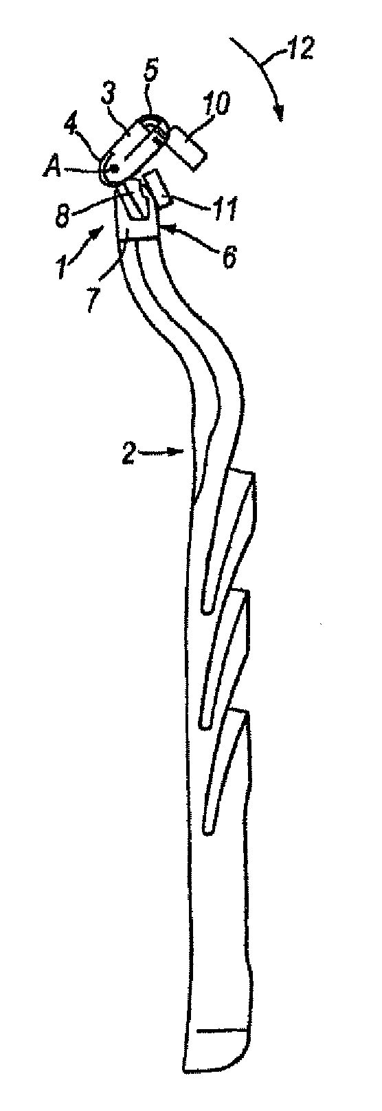
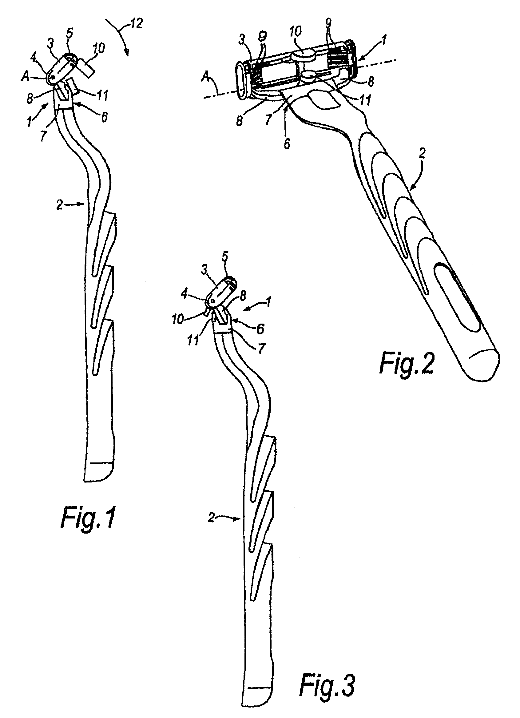
The safety razor illustrated in FIGS. 1 and 2 has a blade unit 1 mounted on a handle 2. The blade unit includes a frame 3 with a guard 4 and a cap 5 and a plurality of blades (not shown) positioned between the guard and cap with their cutting edges parallel to each other, as well known in the art. The blades are movable independently of each other and are urged upwardly with respect to a plane tangential to the guard and cap surfaces by springs 9 which determine the force of the blades against the skin during shaving. The guard preferably includes a strip of elastomeric material with projections such as fins, and the cap may comprise a strip for applying a shaving enhancement product for the skin as previously known.

The blade unit is provided with an attachment member 6 including a hub 7 which is clipped detachably onto the upper end of the handle 2, and a pair of opposed yoke arms 8 extending from the hub 7 and having at their ends pivot journals which are inserted into sockets pro...


PUM


Abstract

A safety razor blade unit mounted for pivotal movement relative to a razor handle is biased to a normal rest position by a magnetic return force generated by a pair of magnets that are so disposed that the return force increases as the pivotal displacement of the blade unit from the rest position increases.

Description

TECHNICAL FIELDThis invention relates to safety razors and it is particularly concerned with safety razors in which a safety razor blade unit including at least one blade with a sharp cutting edge is mounted on a razor handle to be movable pivotally relative to the handle under forces exerted on the blade unit in the course of shaving. A blade unit may have a plurality blades, for example two, three, four or more blades, with straight parallel cutting edges disposed for contact with the skin between guard and cap surfaces also provided on the blade unit. The guard may include a strip of elastomeric material with a surface configuration, for example upstanding projections such as in the shape of fins, to produce a desired interaction with the skin as the blade unit is moved across the skin in the performance of a shaving stroke. The cap surface may include a strip of material containing a shaving enhancement product, such as a lubricant, which can gradually leach out of the strip mat...

Claims


Application Information

Patent Timeline
Patent Type & Authority Patents(United States)
IPC IPC(8): B26B21/52B26B21/22
CPCB26B21/225B26B21/22B26B21/08
Inventor BLACKBURN, RICHARD
Owner THE GILLETTE CO
Why Eureka
Try Eureka