Punch pliers having lower costs of fabrication

a technology of punch pliers and fabrication costs, which is applied in the field of pair of punch pliers, can solve the problems of increasing fabrication costs, inconvenient packaging, transportation and storage of punch pliers, and inconvenient assembly of punch pliers, so as to reduce the waste of materials of the handle and each of the two press members of the control shank assembly, and reduce the cost of fabrication of punch pliers.

Inactive Publication Date: 2011-03-01
QUALIPRO ENTERPRISE
View PDF3 Cites 6 Cited by
  • Summary
  • Abstract
  • Description
  • Claims
  • Application Information

AI Technical Summary

Benefits of technology

[0010]The primary objective of the present invention is to provide a pair of punch pliers having lower costs of fabrication.
[0011]Another objective of the present invention is to provide a pair of punch pliers, wherein the blanks of the handle are juxtaposed to each other on the raw material, and the blanks of each of the two press members of the control shank assembly are juxtaposed to each other on the raw material, so that the wasted materials of the handle and each of the two press members of the control shank assembly are reduced largely, thereby greatly decreasing the costs of fabrication of ...

Problems solved by technology

However, the handle 50 has a forked lower end, and the control shank 60 has a forked upper end so that the handle 50 and the control shank 60 produce many wasted materials as show in FIGS. 10 and 13, thereby increasing the costs of fabrication.
In addition, the two grip portions 54 of the handle 50 have to be inserted into the forked upper...

Method used


Image

  • Punch pliers having lower costs of fabrication
  • Punch pliers having lower costs of fabrication
  • Punch pliers having lower costs of fabrication

Examples


Embodiment Construction

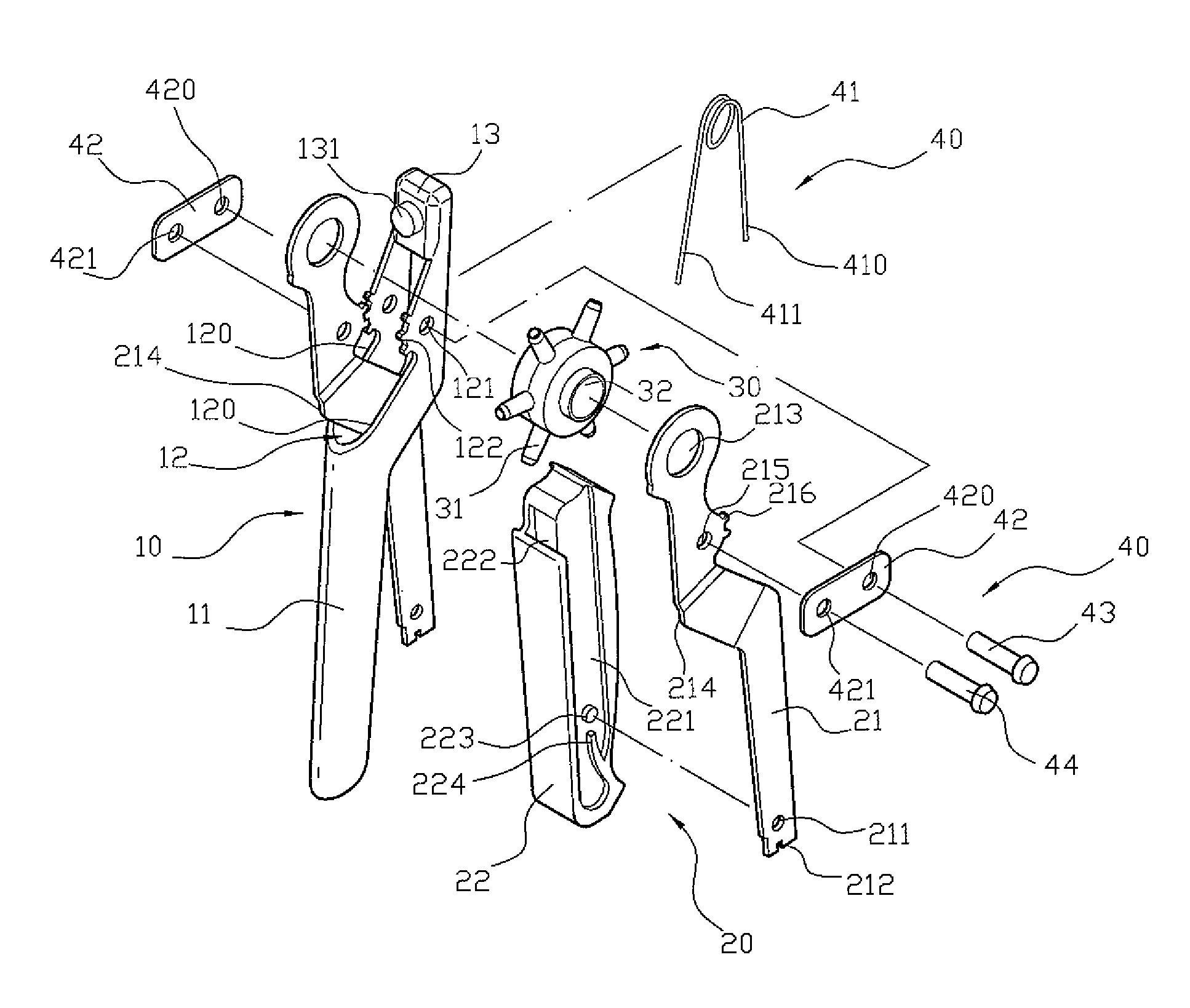
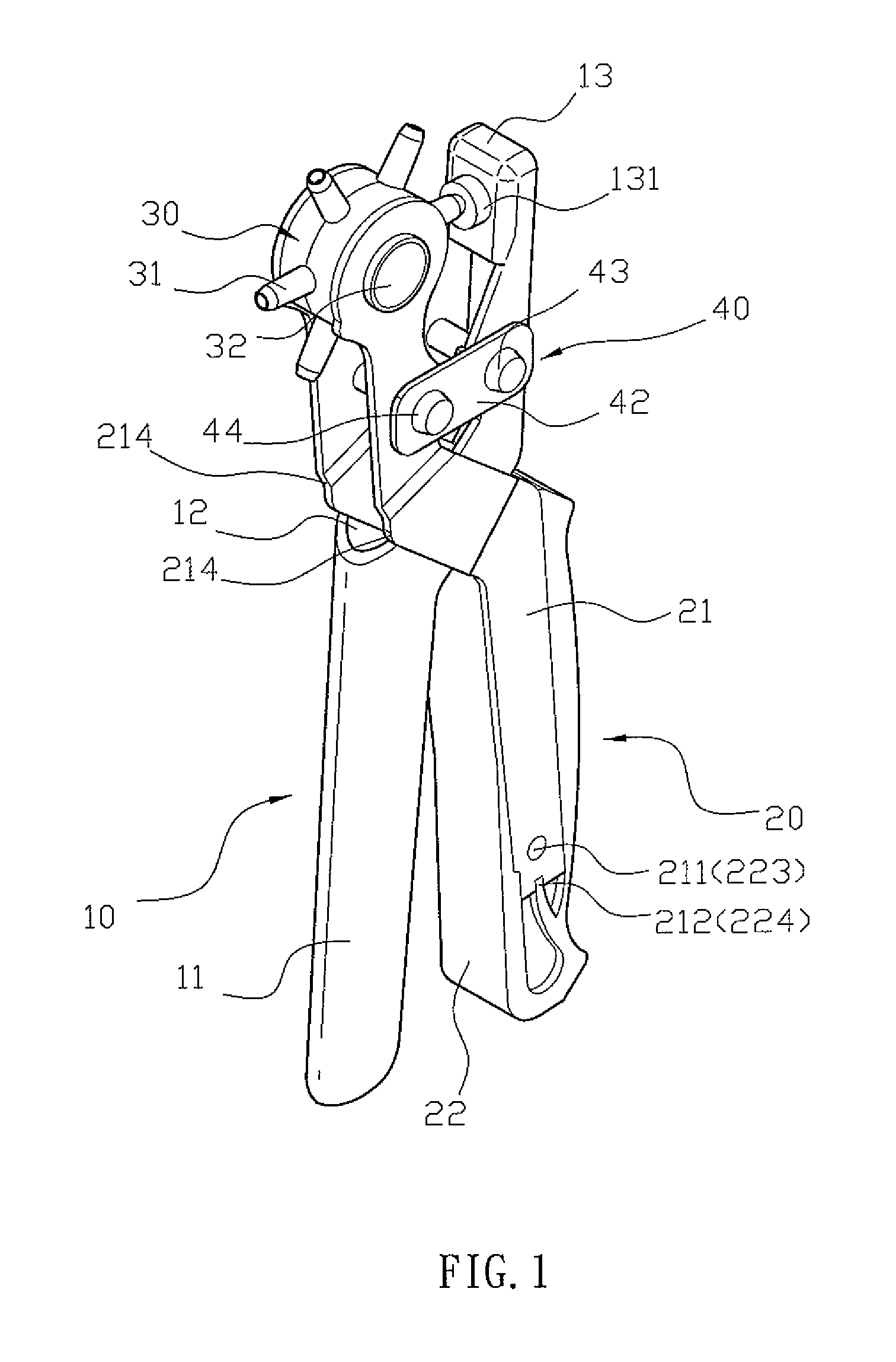
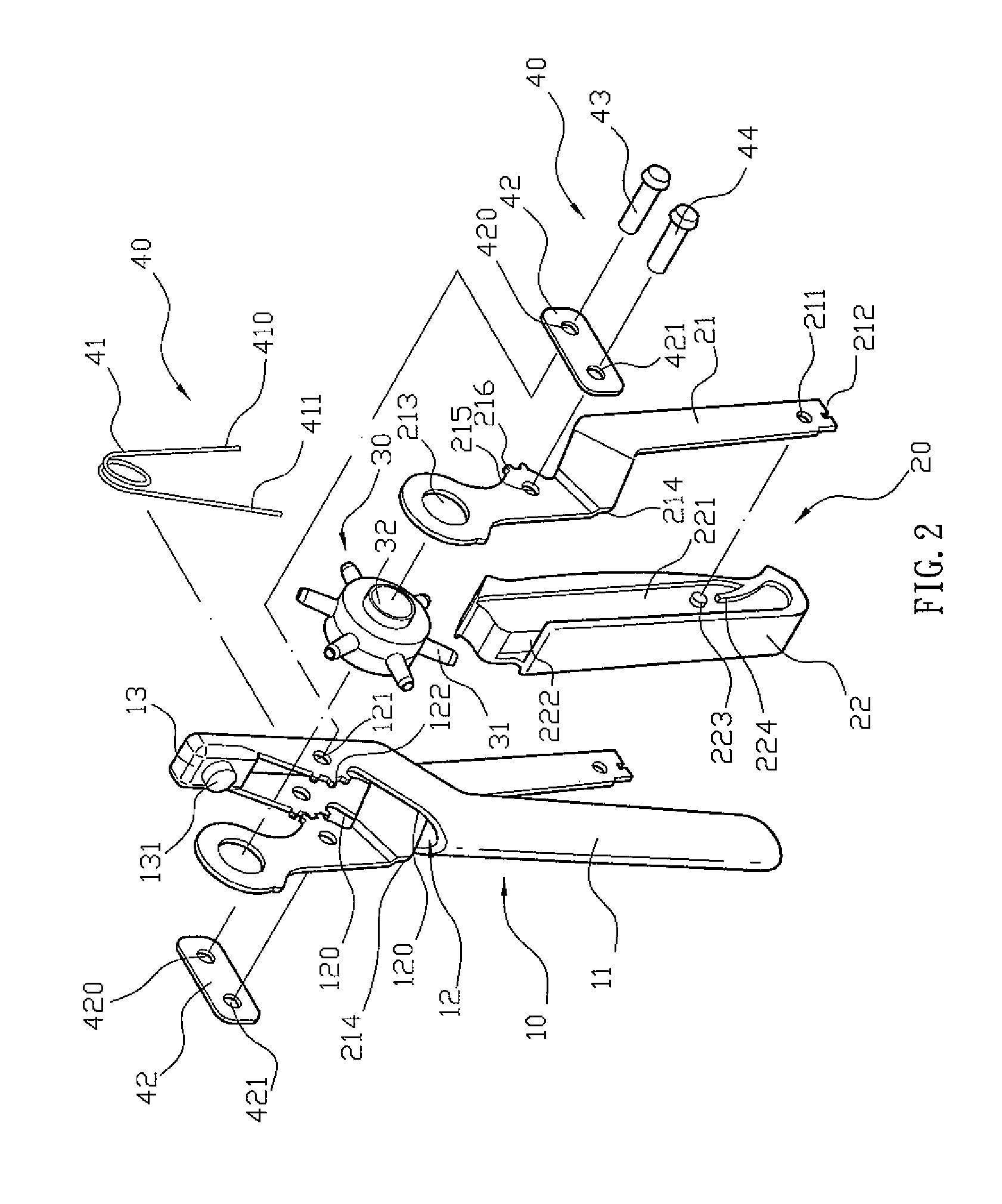
[0031]Referring to the drawings and initially to FIGS. 1 and 2, a pair of punch pliers in accordance with the preferred embodiment of the present invention comprise a handle 10, a control shank assembly 20 pivotally connected with the handle 10, a punching member 30 mounted on the control shank assembly 20 and movable relative to the handle 10, and a connecting device 40 mounted between the handle 10 and the control shank assembly 20 to connect the handle 10 and the control shank assembly 20.

[0032]The handle 10 is a bent sheet plate and has a first end provided with a grip portion 11, a second end provided with a punching seat 13 and a mediate portion provided with a hollow receiving base 12 located between the grip portion 11 and the punching seat 13. The receiving base 12 of the handle 10 has two opposite sidewalls 120. Each of the two sidewalls 120 of the receiving base 12 of the handle 10 is provided with a first pivot hole 121 and a first toothed portion 122. The punching seat ...


PUM


Abstract

A pair of punch pliers include a handle, a control shank assembly, a punching member, and a connecting device. The handle has a first end provided with a grip portion, a second end provided with a punching seat and a mediate portion provided with a hollow receiving base. The control shank assembly includes two press members each pivotally mounted on the receiving base of the handle, and a press block mounted between the two press members. Thus, the blanks of the handle are juxtaposed to each other, and the blanks of each of the two press members of the control shank assembly are juxtaposed to each other, so that the wasted materials of the handle and each of the two press members are reduced largely, thereby decreasing the costs of fabrication of the punch pliers.

Description

BACKGROUND OF THE INVENTION[0001]1. Field of the Invention[0002]The present invention relates to a pair of punch pliers and, more particularly, to a pair of punch pliers for punching holes.[0003]2. Description of the Related Art[0004]A pair of conventional punch pliers in accordance with the prior art shown in FIG. 9 comprise a handle 50, a control shank 60 pivotally connected with the handle 50, a punching member 64 rotatably mounted on the control shank 60 and movable relative to the handle 50, and a connecting device 70 mounted between the handle 50 and the control shank 60 to connect the handle 50 and the control shank 60. The handle 50 has an upper end provided with a punching seat 53, a mediate portion provided with two first pivot holes 51 and two first toothed portions 52 and a forked lower end provided with two grip portions 54. A sleeve 55 is mounted on the two grip portions 54 of the handle 50. The control shank 60 has a forked upper end provided with two second pivot hol...

Claims


Application Information

Patent Timeline
IPC IPC(8): B26B17/00
CPCB25B7/04B25B7/06B26F1/36
Inventor LIN, ROBERT
Owner QUALIPRO ENTERPRISE
Why Eureka
Try Eureka