Apparatus for thermal treatment of an intervertebral disc

a technology of intervertebral discs and apparatuses, which is applied in the field of medical systems and procedures, can solve problems such as pain, damage to probes, and fractures in discs, and achieve the effect of relieving pain and relieving pain

Inactive Publication Date: 2011-03-01
JTC TRUSTEES +1
View PDF34 Cites 10 Cited by
  • Summary
  • Abstract
  • Description
  • Claims
  • Application Information

AI Technical Summary

Benefits of technology

[0010]The present disclosure is directed to an apparatus for treating an intervertebral disc having an inner nucleus pulposus and an outer annulus fibrosus. In general, the apparatus includes a thermal probe defining proximal and distal ends and having a guidable region adjacent the distal end thereof. The guidable region is characterized by having sufficient rigidity to advance within the annulus fibrosus of the intervertebral disc in response to an axial force exerted on the proximal end of the thermal probe while having sufficient flexibility to substantially follow and conform to an azimuthal course defined by the natural striata of the annulus fibrosus. The thermal probe is adapted for connection to a thermal energy source to provide thermal energy to the annulus fibrosus to alleviate pain associated with the intervertebral disc. Preferably, the guidable region includes a thermal transmitting element for transmitting thermal energy to the intervertebral disc. The guidable region may include a helical spring.

Problems solved by technology

Fissures or cracks within the disc caused by age, mechanical trauma, or disc degeneration are believed to be associated with painful symptoms.
Risk of the probe kinking within the disc or straying outside of the disc could result in damage to the probe or injury to the patient.

Method used


Image

  • Apparatus for thermal treatment of an intervertebral disc
  • Apparatus for thermal treatment of an intervertebral disc
  • Apparatus for thermal treatment of an intervertebral disc

Examples


Embodiment Construction

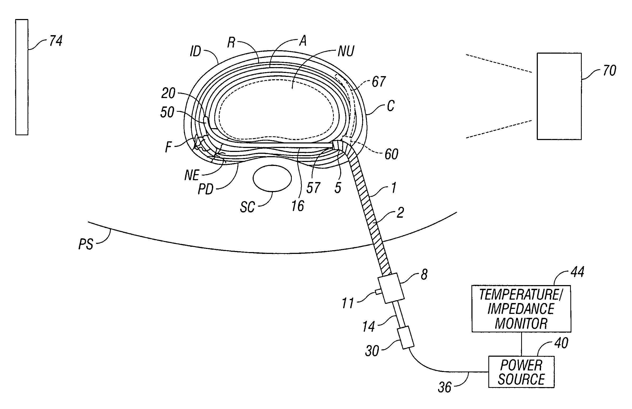
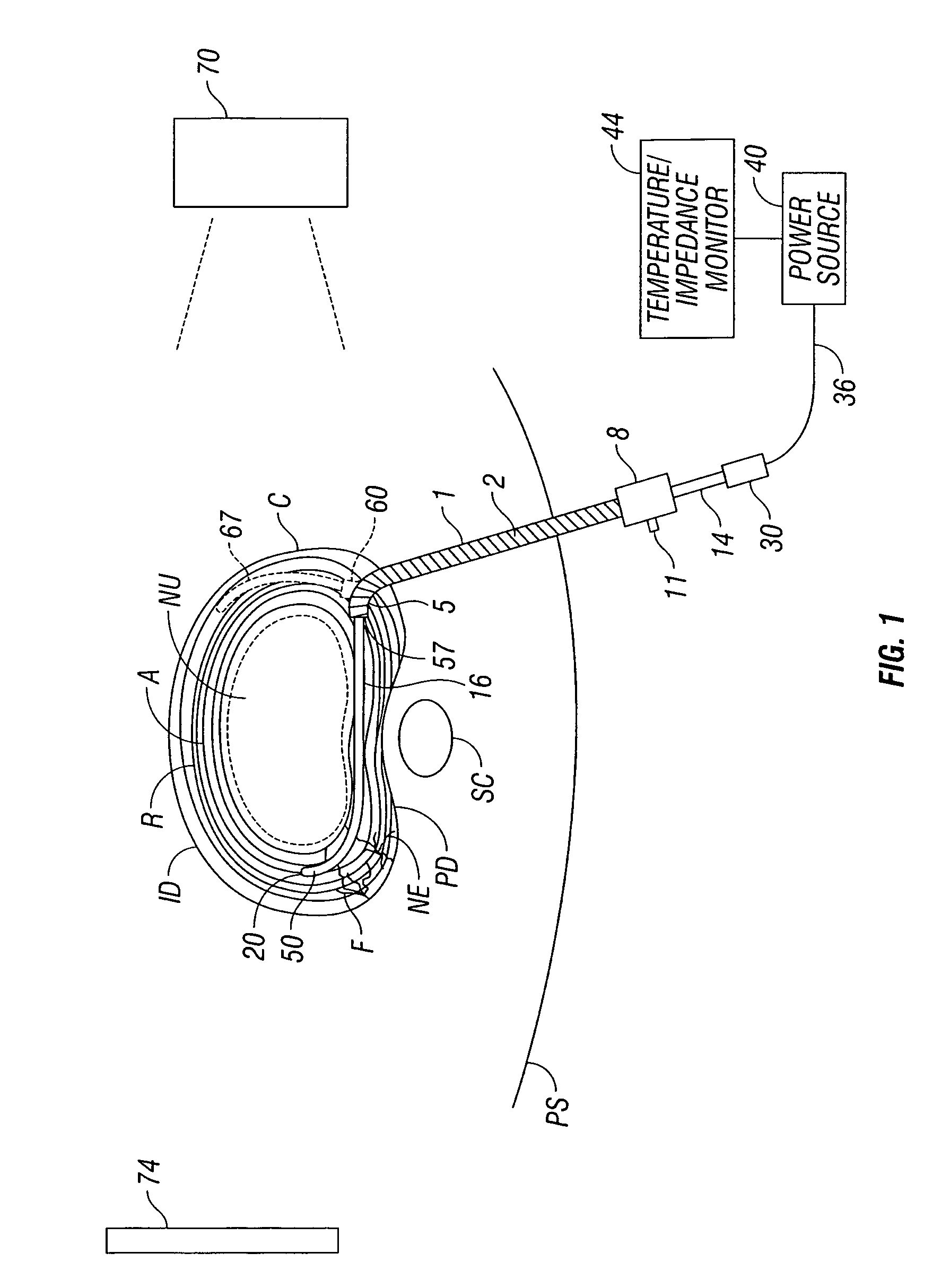
[0017]Referring to FIG. 1, the apparatus of the present disclosure introduced into the intervertebral disc is illustrated. Cannula 1 has an insulated portion represented by the hatched area 2 over a portion of its shaft. Cannula has a rigid curved tip portion 5 and a hub 8 with index pin 11 to indicate the direction of the curved portion 5 of the cannula tip. It is inserted manually and percutaneously through the patient's skin PS from the posterior or posterior / lateral position. This is typically done under flouroscopic control. The cannula tip 5 is inserted into the intervertebral disc ID and is placed in the outer annular portion A, referred to as the annulus fibrosus of the disc. The outer annular portion is composed of multiple cartilaginous rings R defining the natural striata of the disc annulus. In the interior of the disc, inside of the dashed line in FIG. 1, is the NU nucleus or nucleus pulposus of the disc, which has a softer consistency than the annulus. The nucleus NU o...


PUM


Abstract

An apparatus and method for treating an intervertebral disc having an inner nucleus pulposus and an outer annulus fibrosus includes a thermal probe defining proximal and distal ends and having a guidable region adjacent the distal end thereof. The guidable region is characterized by having sufficient rigidity to advance within the annulus fibrosus of the intervertebral disc in response to an axial force exerted on the proximal end of the thermal probe while having sufficient flexibility to substantially follow and conform to an azimuthal course defined by the natural striata of the annulus fibrosus. The thermal probe is adapted for connection to a thermal energy source to provide thermal energy to the annulus fibrosus to alleviate pain associated with the intervertebral disc.

Description

CROSS REFERENCE TO RELATED APPLICATION[0001]This application is a continuation of provisional application Ser. No. 60 / 171,822 filed on Dec. 21, 1999.BACKGROUND[0002]1. Field of the Disclosure[0003]This invention relates generally to advances in medical systems and procedures for prolonging and improving human life. More particularly, this invention relates to a system and method for insertion of a cannula into the intervertebral disc and the insertion of a thermal probe into the disc material to heat the intervertebral disc thereby relieving and treating abnormalities or pain related to the disc.[0004]2. Background of the Disclosure[0005]The use of radiofrequency electrodes for ablation of tissue in the body or for the treatment of pain is known. In a typical situation, a radiofrequency probe or a resistive heating probe commonly constructed in an elongated, cylindrical configuration is inserted into the body to a target tissue which is to be treated or ablated. In the case of a rad...

Claims


Application Information

Patent Timeline
Patent Type & Authority Patents(United States)
IPC IPC(8): A61B18/14A61B18/00A61B17/00A61B18/04A61B18/08A61B18/12A61B18/18A61F7/00
CPCA61B18/1482A61B18/08A61B2017/00026A61B2017/00261A61B2017/00455
Inventor FINCH, PHILIP MICHAELCOSMAN, ERIC R.
Owner JTC TRUSTEES
Why Eureka
Try Eureka