Surgical instrument

a surgical instrument and electrode technology, applied in the field of instruments, can solve the problems of increasing the complexity of the instrument, and achieve the effect of reducing the rate at which the rest of the instrument increases in temperature and effective separation of tissu

Active Publication Date: 2011-03-01
GYRUS MEDICAL LTD
View PDF49 Cites 1215 Cited by
  • Summary
  • Abstract
  • Description
  • Claims
  • Application Information

AI Technical Summary

Benefits of technology

[0007]U.S. Pat. No. 5,304,124 describes an instrument for removing a myoma from the uterus of a patient, the device utilising a cauterising element at the end of a tubular member. This cauterising element is described as being a wire loop, or a “Bovie-type component”. As this device is for the removal of a myoma (leaving the remainder of the uterus intact), the cauterising element will reduce the bleeding from the remainder of the uterus, which will still be vascularly connected to the patient. In contrast, the present invention provides a bipolar electrosurgical device, more suited to the bulk removal of tissue form a uterus which has been resected and will no longer have a vascular supply.
[0010]By providing both a second electrode on the tube, and making the tissue-pulling device effective as the second electrode, each will act as the second electrode at different times. When the tissue is first presented to the tube, the tissue-pulling device will act as the second electrode. Subsequently, as the tissue is pulled into the tube, the bipolar cutting will occur between the first electrode and the second electrode located on the tube. This arrangement ensures that, as the first tissue contact with the tube is established, the bipolar electrode assembly is capable of firing up successfully, and yet continues to be effective as more and more tissue is pulled into the tube.
[0013]The tissue-pulling device is preferably a pair of jaw members movable between open and closed positions, the jaw members conveniently being mounted on a rod extending through the tube. The jaws can be closed around tissue, grasping it firmly, and the rod retracted within the tube to cause the tissue to be severed by the electrosurgical electrode assembly at the distal end of the tube. Alternatively, the tissue-pulling device comprises a screw member rotatable with respect to the tube. Rotation of the screw member has the effect of pulling tissue into the tube.
[0014]The tube conveniently has an end face which is angled with respect to the longitudinal axis of the tube, preferably at an angle of between 30 and 60 degrees to the longitudinal axis, and typically at 45 degrees thereto. This angled end face helps to ensure that the initial contact between the tissue and the electrode assembly is a point contact, thereby assisting with the firing-up of the electrode assembly into a cutting or vaporisation mode and ensuring effective separation of the tissue.
[0015]The stationary tube alternatively has an end face with an undulating circumference, typically a castellated or alternatively a wave-like circumferential surface. In one convenient arrangement, the circumference undulates substantially in the form of a sine wave. These different end profiles each help to provide one or more gradually-progressing point of contact, as opposed to a uniform contact over the whole of the end circumference, thereby assisting with the electrosurgical cutting of tissue.
[0016]The first electrode preferably has a distal portion including a plurality of apertures disposed around its circumference, preferably in one or more rows of apertures set back from the end of the tube. The apertures are conveniently circular holes, or alternatively elongate slots, and the apertures in one row are preferably radially offset from the apertures in an adjacent row. The apertures seek to ensure that heat is not conducted away too rapidly from the distal circumference of the first electrode, thereby keeping the active electrode at a high temperature and reducing the rate at which the remainder of the instrument increases in temperature.

Problems solved by technology

This rotation of the electrode necessitates a mechanical drive arrangement, which increases the complexity of the instrument.

Method used


Image

  • Surgical instrument
  • Surgical instrument
  • Surgical instrument

Examples


Embodiment Construction

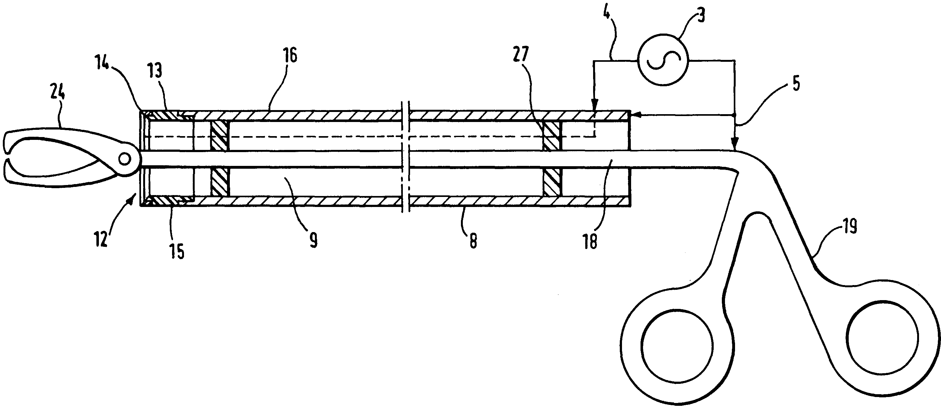
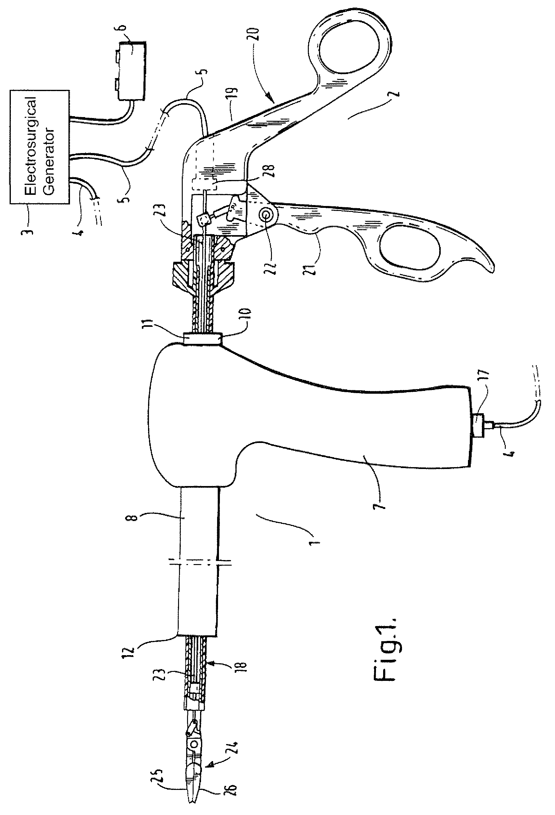
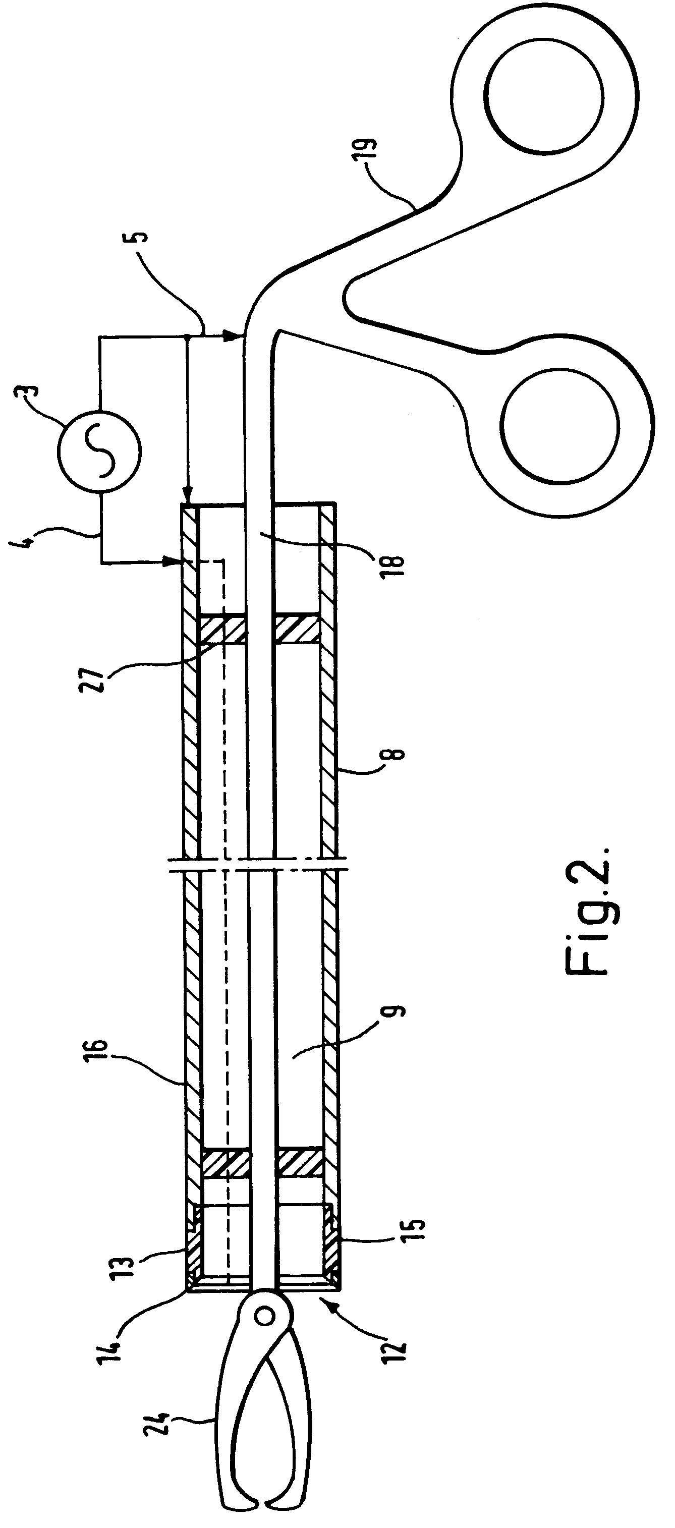
[0032]Referring to FIG. 1, a morcellating system comprises a morcellating device shown generally at 1, a tissue-pulling device shown generally at 2, and an electrosurgical generator 3. The generator 3 is connected to the morcellating device 1 by means of cable 4, and to the tissue-pulling device 2 by means of cable 5. The generator 3 is controlled by means of footswitch 6.

[0033]As shown in FIGS. 1 and 2, the morcellating device 1 comprises a handle 7 and a cylindrical tube 8. The cylindrical tube 8 is hollow, and defines a lumen 9 therein. The proximal end 10 of the tube 8 extends from the handle 7 as shown at 11, and the distal end 12 of the tube is provided with an electrosurgical electrode assembly 13. The electrosurgical electrode assembly 13 comprises an active tissue-cutting electrode 14, and an insulation member 15, both extending around the circumference of the tube 8. The insulation member 15 separates the electrode 14 from the remainder of the tube 8, which acts as a retur...


PUM


Abstract

A device for morcellating tissue within a body cavity of a patient comprises a stationary tube having a distal end portion, and a bipolar electrosurgical electrode assembly located at the distal end of the tube. The electrosurgical electrode assembly comprises first and second electrodes separated by an insulation member, the bipolar electrosurgical electrode assembly extending around the circumference of the distal edge of the tube. When an electrosurgical cutting voltage is applied to the electrode assembly, and relative movement is initiated between the tube and the tissue, a core of severed tissue is formed within the tube such that it can be removed from the body cavity of the patient. A tissue-pulling device such as a jaw assembly can be employed to pull tissue against the distal end of the tube.

Description

RELATED APPLICATIONS[0001]This application is a continuation-in-part of application Ser. No. 10 / 924,954, filed Aug. 25, 2004, now abandoned which claims priority to U.K application 0411270.2, filed May 20, 2004, the entire contents of which are hereby incorporated by reference in this application.BACKGROUND OF THE INVENTION[0002]This invention relates to a bipolar electrosurgical instrument for use in the bulk removal of tissue, as in a laparoscopic hysterectomy.[0003]In a laparoscopic hysterectomy, the body of the uterus is resected from the stump or fundus, and then removed from the operative site. To enable the uterus to be removed through a limited surgical opening, it is desirable to morcellate it into relatively smaller pieces of tissue, which are easier to remove. The present invention relates to an instrument and method for morcellating and removing a uterus.[0004]U.S. Pat. Nos. 5,957,884, 6,007,512 and 6,036,681 are examples of morcellating devices in which an element carry...

Claims


Application Information

Patent Timeline
Patent Type & Authority Patents(United States)
IPC IPC(8): A61B18/14A61B17/28A61B17/32A61B17/42
CPCA61B18/1442A61B18/1485A61B17/29A61B17/320016A61B17/32053A61B2017/320775A61B2017/4216A61B2018/1412
Inventor HALL, MATTHEW R.MARSHALL, MARK G.GOBLE, COLIN C. O.AMOAH, FRANCISVARNEY, KELVIN J.EBBUTT, JULIAN MARK
Owner GYRUS MEDICAL LTD
Why Eureka
Try Eureka