
Apparatus and method for deployment of a bronchial obstruction device

a bronchial obstruction and apparatus technology, applied in the field of bronchial obstruction apparatus and method, can solve the problems of copd, no cure, and airflow obstruction in copd, and achieve the effect of reducing the risk of bronchial obstruction

Inactive Publication Date: 2011-03-01
GYRUS ACMI INC (D B A OLYMPUS SURGICAL TECH AMERICA)
View PDF250 Cites 100 Cited by
  • Summary
  • Abstract
  • Description
  • Claims
  • Application Information

AI Technical Summary

Problems solved by technology

Chronic Obstructive Pulmonary Disease (COPD) has become a major cause of morbidity and mortality in the United States over the last three decades.
The airflow obstruction in COPD is due largely to structural abnormalities in the smaller airways.
COPD is a progressive disease and currently has no cure.
Unfortunately, there is no evidence that early, regular use of pharmacotherapy will alter the progression of COPD.
Although the surgery was deemed promising, the procedure was abandoned.
However, the procedure has fallen out of favor due to the fact that Medicare stopping reimbursing for LVRS.
Unfortunately, data is relatively scarce and many factors conspire to make what data exists difficult to interpret.
However, the surgery is not without potential complications.
Lung tissue is very thin and fragile.
Hence, it is difficult to suture after sectioning.
This gives rise to potential infection and air leaks.
In fact, nearly thirty percent (30%) of such surgeries result in air leaks.
Unfortunately, this consideration is given for only those with advanced COPD.
Given the limited availability of donor organs, lung transplant is far from being available to all parties.
The air passageway may be obstructed by placing a bronchial obstruction device in the air passageway.
Patients suffering from COPD generally have compromised health.

Method used


Image

  • Apparatus and method for deployment of a bronchial obstruction device
  • Apparatus and method for deployment of a bronchial obstruction device
  • Apparatus and method for deployment of a bronchial obstruction device

Examples


Embodiment Construction

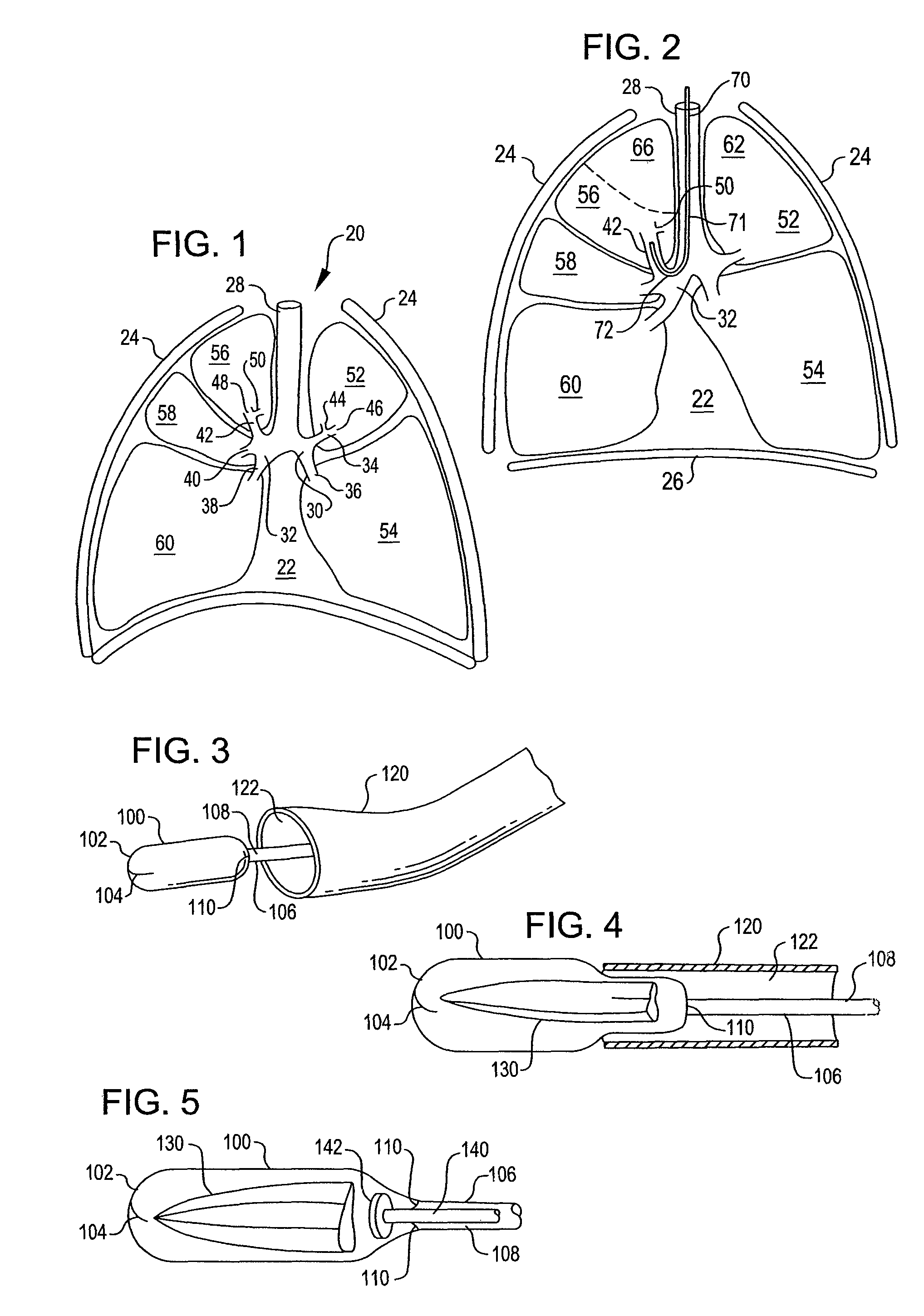
[0035]Referring now to FIG. 1, it is a sectional view of a healthy respiratory system. The respiratory system 20 resides within the thorax 22 which occupies a space defined by the chest wall 24 and the diaphragm 26.

[0036]The respiratory system 20 includes the trachea 28, the left mainstem bronchus 30, the right mainstem bronchus 32, the bronchial branches 34, 36, 38, 40, and 42 and sub-branches 44, 46, 48, and 50. The respiratory system 20 further includes left lung lobes 52 and 54 and right lung lobes 56, 58, and 60. Each bronchial branch and sub-branch communicates with a respective different portion of a lung lobe, either the entire lung lobe or a portion thereof. As used herein, the term “air passageway” is meant to denote either a bronchial branch or sub-branch which communicates with a corresponding individual lung lobe or lung lobe portion to provide inhaled air thereto or conduct exhaled air therefrom.

[0037]Characteristic of a healthy respiratory system is the arched or inwa...


PUM


Abstract

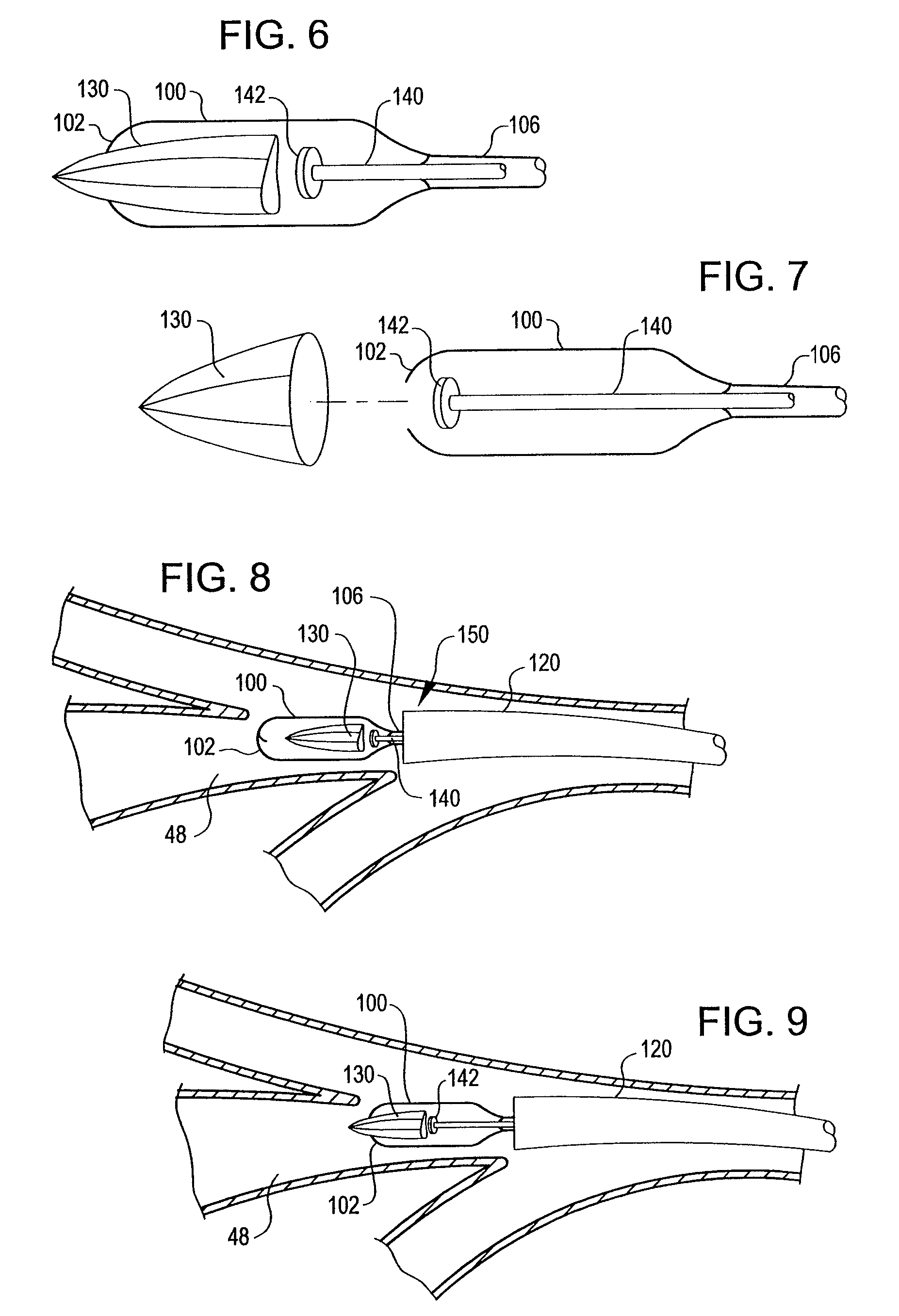
An apparatus and method deploy a self-expandable bronchial obstruction device in an air passageway. The apparatus includes a catheter configured to be passed down the trachea. The apparatus further includes a capsule for housing the self-expandable bronchial obstruction device in a sterile environment. The capsule is configured to be advanced down the catheter. The capsule further includes a tubular extension. The capsule has a breakable seam so as to release the bronchial obstruction device in the air passageway upon a proximal force being exerted upon the bronchial obstruction device. The method includes guiding a conduit down a trachea into the air passageway. The method further includes advancing a capsule having a bronchial device therein down an internal lumen of the conduit into the air passageway. The method further includes releasing the bronchial device from the capsule. The method further includes deploying the bronchial device into the air passageway.

Description

CROSS-REFERENCE TO RELATED APPLICATIONS[0001]This application is a continuation of U.S. patent application Ser. No. 10 / 418,929, filed Apr. 17, 2003, now abandoned titled BRONCHIAL OBSTRUCTION DEVICE DEPLOYMENT SYSTEM AND METHOD, which is a continuation of U.S. patent application Ser. No. 10 / 052,875, filed on Oct. 25, 2001, now U.S. Pat. No. 6,592,594, titled BRONCHIAL OBSTRUCTION DEVICE DEPLOYMENT SYSTEM AND METHOD. The entire disclosure of each of the above-noted prior applications is hereby incorporated by reference herein and made a part of this specification.BACKGROUND OF THE INVENTION[0002]1. Field of the Invention[0003]The present invention is generally directed to a treatment of Chronic Obstructive Pulmonary Disease (COPD). The present invention is more particularly directed to an apparatus and method for deploying a bronchial device.[0004]2. Description of the Related Art[0005]Chronic Obstructive Pulmonary Disease (COPD) has become a major cause of morbidity and mortality in...

Claims


Application Information

Patent Timeline
Patent Type & Authority Patents(United States)
IPC IPC(8): A61B17/12A61B17/00A61B19/00A61B17/24
CPCA61B17/12022A61B17/12104A61B17/12172A61B2019/307A61B2017/1205A61B2017/242A61B17/24A61B2090/037A61F2002/043A61M29/02A61M2029/025
Inventor RIMBAUGH, JENNIDEVORE, LAURI J.
Owner GYRUS ACMI INC (D B A OLYMPUS SURGICAL TECH AMERICA)
Learn More