Multistage multicontroller variable impactor

a multi-controller, impactor technology, applied in the direction of filtration separation, auxillary pretreatment, separation process, etc., can solve the problems of large pressure drop, inability to optimize efficiency early in the life of the engine, and the separation actually begins to perform with higher efficiency, so as to achieve controllable pressure drop, improve performance, and high efficiency

Active Publication Date: 2011-03-01
CUMMINS FILTRATION IP INC
View PDF60 Cites 22 Cited by
  • Summary
  • Abstract
  • Description
  • Claims
  • Application Information

AI Technical Summary

Benefits of technology

[0005]In one parent embodiment, multiple stages allow the impactor design to be optimized for several points in the life of the engine. For example, in one parent embodiment, the blowby gas is exposed to fewer nozzles in the beginning when pressure and flow are lower. As pressure increases, more stages are opened. This means that efficiency can be high from the beginning of life, and pressure drop is controlled as the engine wears. This parent embodiment provides improved performance by delivering a more consistent efficiency and pressure drop over the life of the engine.

Problems solved by technology

When this happens, the separator actually begins to perform with higher efficiency, but also has a larger pressure drop.
This means the efficiency early in the life of the engine may not be optimized.

Method used


Image

  • Multistage multicontroller variable impactor
  • Multistage multicontroller variable impactor
  • Multistage multicontroller variable impactor

Examples


Embodiment Construction

Parent Applications

[0048]The following description of FIGS. 1-37 is taken from the above noted parent applications.

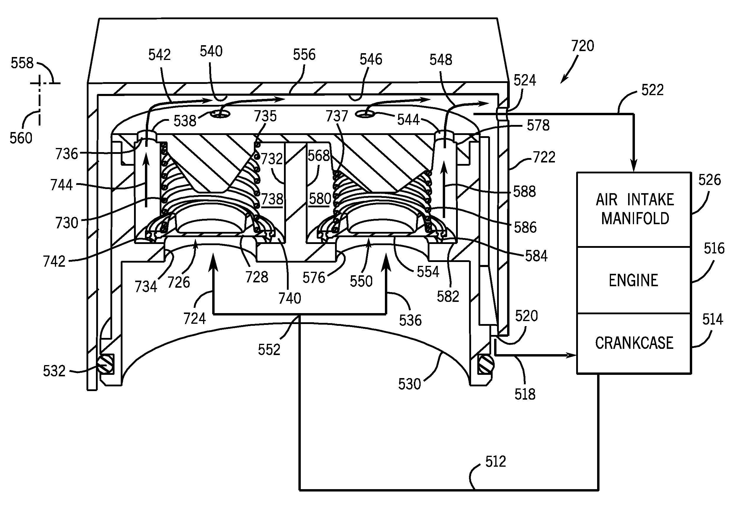
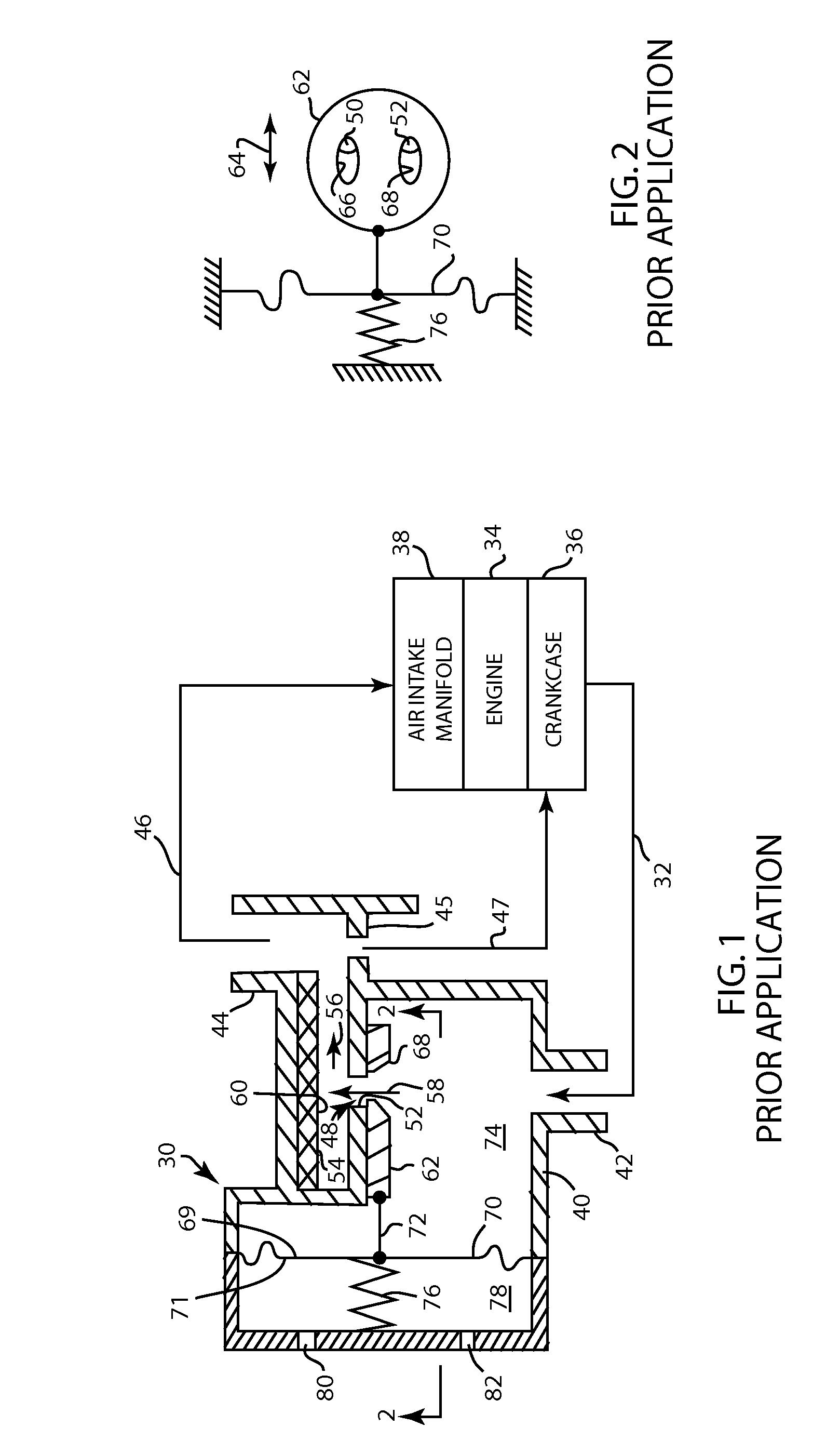
[0049]FIG. 1 shows an inertial gas-liquid impactor separator 30 for coalescing and removing liquid particles from a gas-liquid stream 32, shown in an exemplary crankcase ventilation separation application for an internal combustion engine 34. In such application, it is desired to vent blow-by gases from crankcase 36 of engine 34. Untreated, these gases contain particulate matter in the form of oil mist and soot. It is desirable to control the concentration of the contaminants, especially if the blow-by gases are to be recirculated back to the engine's air intake system, for example at air intake manifold 38. The oil mist droplets are generally less than 5μ in diameter, and hence are difficult to remove using conventional fibrous filter media while at the same time maintaining low flow resistance as the media collects and becomes saturated with oil and contaminants.

[0050...


PUM

PropertyMeasurementUnit
diameteraaaaaaaaaa
pressureaaaaaaaaaa
biasing forceaaaaaaaaaa

Abstract

An inertial gas-liquid impactor separator and method is provided, including multiple stages and multiple variable flow controllers.

Description

CROSS-REFERENCE TO RELATED APPLICATIONS[0001]This application is a continuation-in-part of U.S. patent application Ser. No. 11 / 622,051, filed Jan. 11, 2007, now U.S. Pat. No. 7,648,543 which is a continuation-in-part of U.S. patent application Ser. No. 11 / 168,688, filed Jun. 28, 2005, now U.S. Pat. No. 7,473,291 which is a continuation-in-part of U.S. patent application Ser. No. 10 / 946,603, filed Sep. 21, 2004, now U.S. Pat. No. 7,238,216.BACKGROUND AND SUMMARY[0002]The above noted parent applications related to inertial gas-liquid impactor separators for removing liquid particles from a gas-liquid stream, including in engine crankcase ventilation separation applications, including closed crankcase ventilation (CCV) and open crankcase ventilation (OCV) systems.[0003]Inertial gas-liquid separators are known in the prior art. Liquid particles are removed from a gas-liquid stream by accelerating the stream or aerosol to high velocities through nozzles or orifices and directing same aga...

Claims


Application Information

Patent Timeline
Patent Type & Authority Patents(United States)
IPC IPC(8): B01D51/00B01D46/46
CPCB01D45/08F01M13/00F01M13/0011F01M13/04F01M13/023Y10S55/14
Inventor STEFFEN, BRYAN P.SEVERANCE, STEPHANIE F.RUTZINSKI, RYAN W.
Owner CUMMINS FILTRATION IP INC
Why Eureka
Try Eureka