Punch press, method of replacing punch and die for punch press, and punch system

a punch press and die technology, applied in the direction of metal-working machine components, manufacturing tools, shaping tools, etc., can solve the problems of inability to effectively suck out punched materials, inability to automate a program, and lowered working efficiency, so as to save the space of the punch and die set

Inactive Publication Date: 2011-03-08
AMADA CO LTD
View PDF22 Cites 24 Cited by
  • Summary
  • Abstract
  • Description
  • Claims
  • Application Information

AI Technical Summary

Benefits of technology

[0065]Accordingly, saving of a space for the punch and die set accommodating apparatus can be achieved.

Problems solved by technology

For this reason, since the downward forming is particularly conducted in another step, or such a movement or working order that the interference can be avoided is edited manually by devising a program, there is a problem that a working efficiency is lowered due to occurrence of a skilled work required.
That is, in an automatic programming apparatus, a movement locus is determined such that a working time, namely a material movement distance to the next working coordinates is made shortest, but it becomes impossible to automate a program, because such a movement locus that a problem of a catching or the like can be solved can not be considered.
Further, as shown in FIG. 5, in the turret punch press 501, since a relief clearance is provided such that a punched-out scrap is not caught by a disc support 531 supporting the lower portion turret 505L from its lower side at a time of working, there is a problem that the punched-out material can not be sucked effectively.
Moreover, in case that indexing functions for angular direction of each punch and die set (auto-indexes) are provided on the upper and lower portion turrets 505U, 505L, there is a problem that parts such as a worm gear for indexing and the like increases, which makes the turret punch press 501 expensive.
Further, since a space is occupied by the gear or the like, the number of punch and die set stations is largely reduced (to about a half of the number), which causes a case that the working can not be conducted unless punch and die set exchanging is performed.
As a result, there is a problem that productivity reduction is caused.
On the other hand, since only one punch and die set is usually held in the single head constitution, there is a problem that die exchange must frequently be performed in a sheet working of a plate metal using a plurality of dies.
For this reason, a punch and die set called a multi-tool where a plurality of dies are equipped in one punch and die set is also used, but since the punch and die set is constituted such that other dies are built in one punch and die set, there is a problem that dies other than a punch and die set having a small size can not be equipped.
Further, in case that one punch and die set in the multi-tool is selected according to a program and there is not a punch and die set to be used next in the multi-tool, the punch and die set must be exchanged to another punch and die set, which is not so effective for reduction of a punch and die set exchanging time.
However, since workpiece dampers can not be moved near a punch and die set due to a relationship where dies with a small size have been structurally equipped in one main punch and die set frame, there is a defect that a region which can not be worked (a dead zone) increases, and there is a problem that the dead zone restrains a program, which makes it difficult to use the multi-tool in a real working.
On the other hand, in the single head constitution, since one punch and die set is merely held usually, a punch and die set accommodating apparatus accommodating a plurality of dies is required in a sheet working of a plate metal using a plurality of dies, in which there is a problem that a punch and die set accommodating apparatus which accommodates many dies is required, which results in large-sizing of the apparatus.
Moreover, since dies must frequently be exchanged, there is a problem that working efficiency is reduced.

Method used


Image

  • Punch press, method of replacing punch and die for punch press, and punch system
  • Punch press, method of replacing punch and die for punch press, and punch system
  • Punch press, method of replacing punch and die for punch press, and punch system

Examples


Embodiment Construction

[0097]Embodiments of this invention will be explained in detail below with reference to the drawings.

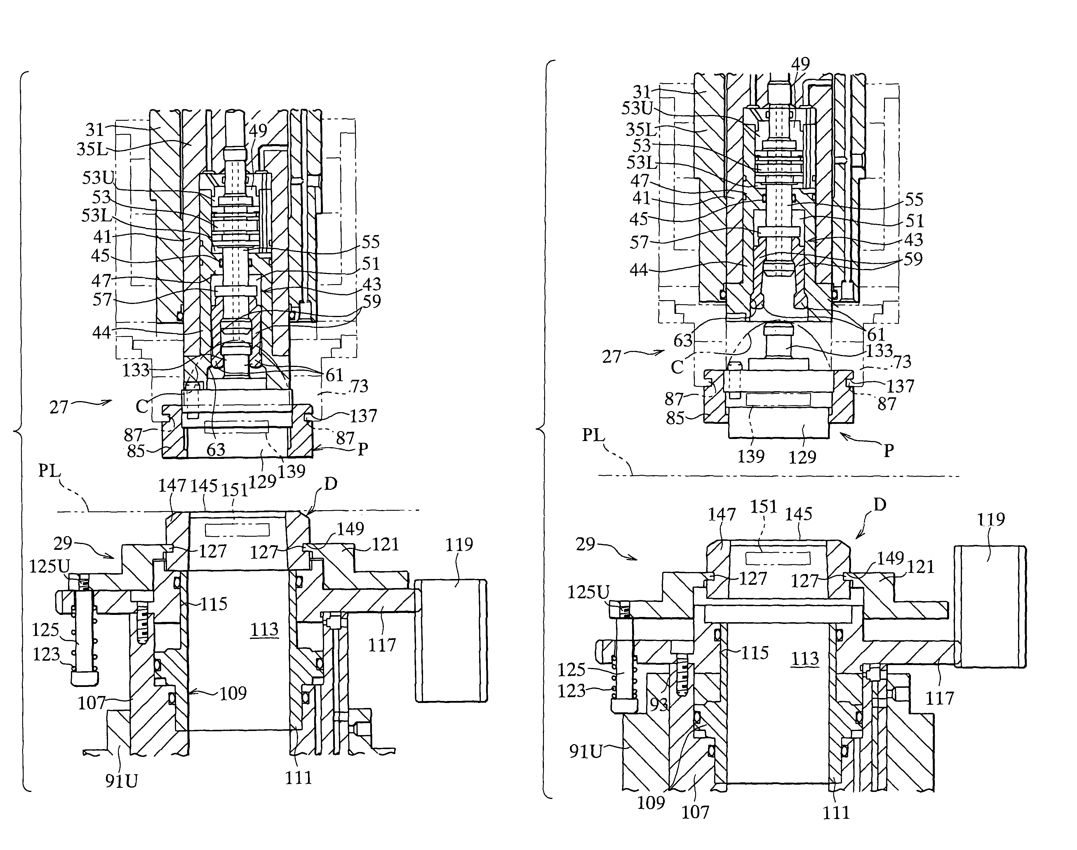
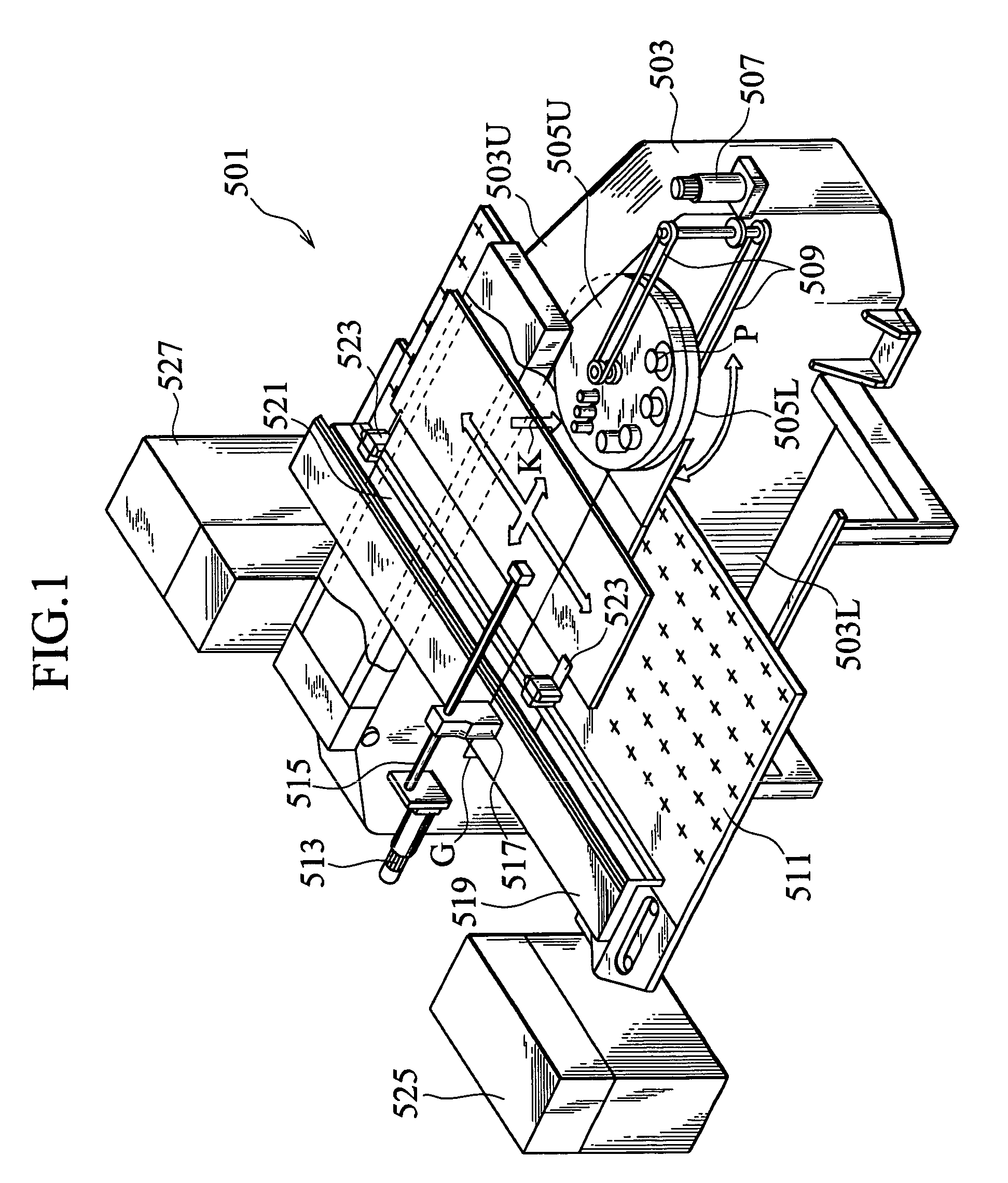
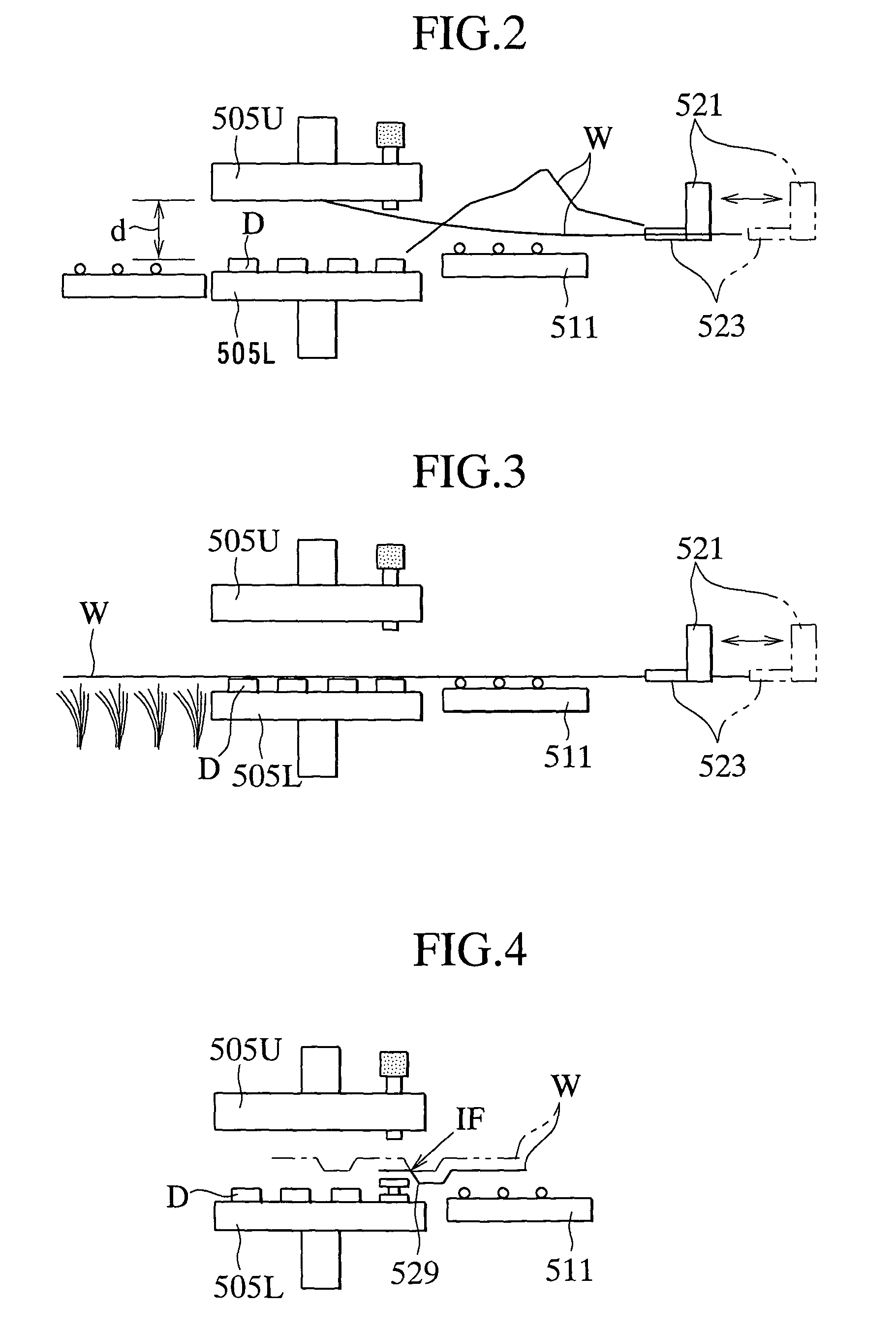
[0098]In FIG. 6 and FIG. 7, a punch press 1 according to this invention is shown. In the punch press 1, a gap G is provided between an upper portion frame 5 and a lower portion frame 7 at a center portion of a frame 3 formed in a gate shape. A punch P is supported at a working position K in the gap G by the upper portion frame 5 so as to be movable vertically, and a die D is supported by the lower portion frame 7 so as to be movable vertically.

[0099]On the other hand, a workpiece moving and positioning apparatus 9 which supports and positions a workpiece W to be worked is provided in the gap G. In the workpiece moving and positioning apparatus 9, a carriage base 15 is provided at a right end portion of a working table 11 in FIG. 6 such that the workpiece table 11 can be moved along a pair of guide rails 13 provided in an Y-axis direction (right and left directions in FIG. 6), and the...


PUM

PropertyMeasurementUnit
heightaaaaaaaaaa
sizeaaaaaaaaaa
thicknessaaaaaaaaaa

Abstract

A punch press provided with a punch and die set taking-out/taking-in apparatus 291; a punch taking-out/taking-in arm 367 for performing taking-out/taking-in of a punch P; and a die taking-out/taking-in arm 369 for performing taking-out/taking-in of a die D, wherein taking-out/taking-in of many punches P, dies D accommodated in a punch and die set accommodating portion 282 of a rack 283 is performed by pivoting a punch holding arm 279 which holds a punch P and a die holding arm 281 which holds a die D in a punch and die set exchanging apparatus 23 forward or backward; and delivery of a die is performed between the punch and die set taking-out/taking-in apparatus 291 and the punch and die set exchanging apparatus 23.

Description

TECHNICAL FIELD[0001]The present invention relates to a punch press for performing punching work on a workpiece in cooperation of a punch and a die, a punch / die exchanging method for to a punch press, and a punch system.BACKGROUND ART[0002]In FIG. 1, a turret punch press 501 serving as a punch press which is conventionally well-known is shown. The turret punch press 501 is provided in a standing manner with a frame 503 having a gap portion G at a central portion thereof, and an upper portion turret 505U which is supported at an upper portion frame 503U in a rotationally indexable manner and is equipped with a plurality of punches P is provided at the gap portion G. Further, a lower portion turret 505L which is equipped with a plurality of dies D (refer to FIG. 2 to FIG. 5) is provided in a rotationally indexable manner on a lower portion frame 503L so as to opposed to the upper portion turret 505U. The upper portion turret 505U and the lower portion turret 505L are rotated synchrono...

Claims


Application Information

Patent Timeline
Patent Type & Authority Patents(United States)
IPC IPC(8): B21D5/01B21D28/12B21D28/34B21D37/04B21D37/14
CPCB21D28/12B21D28/34B21D37/04B21D37/145Y10T83/8703Y10T83/8727Y10T83/8748Y10T83/8835Y10T83/8858Y10T83/9423Y10T83/9425B23Q3/15573B23Q3/15536
Inventor IKEDA, NOBUYUKIISHIWATA, YOSHIHISAWAKAO, JUN
Owner AMADA CO LTD
Why Eureka
Try Eureka