Laminates of films having improved resistance to bending in all directions and methods and apparatus for their manufacture

a technology of laminates and films, applied in the field of flexible laminates, can solve problems such as doubt that a wavelength lower than this can be achieved

Inactive Publication Date: 2011-03-08
RASMUSSEN OB
View PDF60 Cites 45 Cited by
  • Summary
  • Abstract
  • Description
  • Claims
  • Application Information

AI Technical Summary

Problems solved by technology

It is very doubtful that a wavelength lower than this can be achieved by the method disclosed in this patent, in which the first bonding process takes place by the use of a row of many sealer bars supported and transported by a belt.

Method used


Image

  • Laminates of films having improved resistance to bending in all directions and methods and apparatus for their manufacture
  • Laminates of films having improved resistance to bending in all directions and methods and apparatus for their manufacture
  • Laminates of films having improved resistance to bending in all directions and methods and apparatus for their manufacture

Examples


example 1

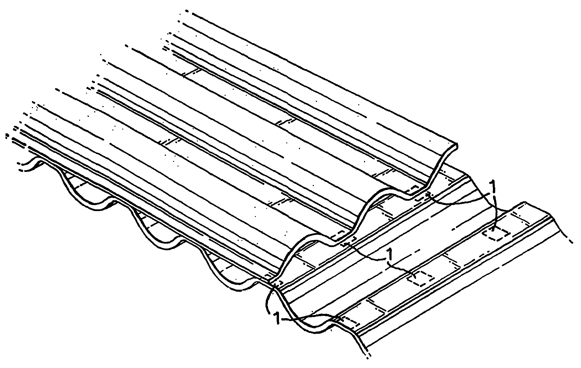
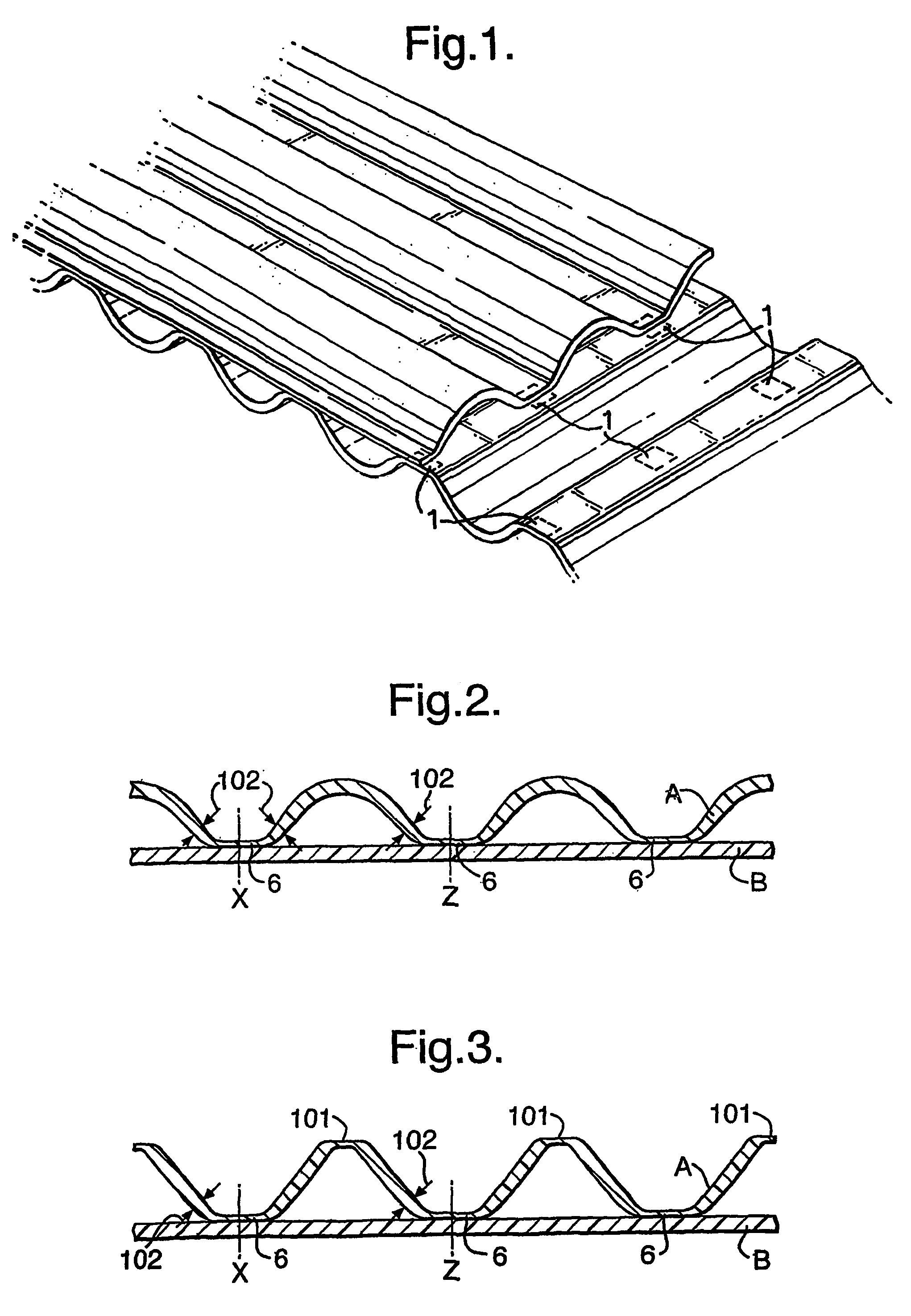
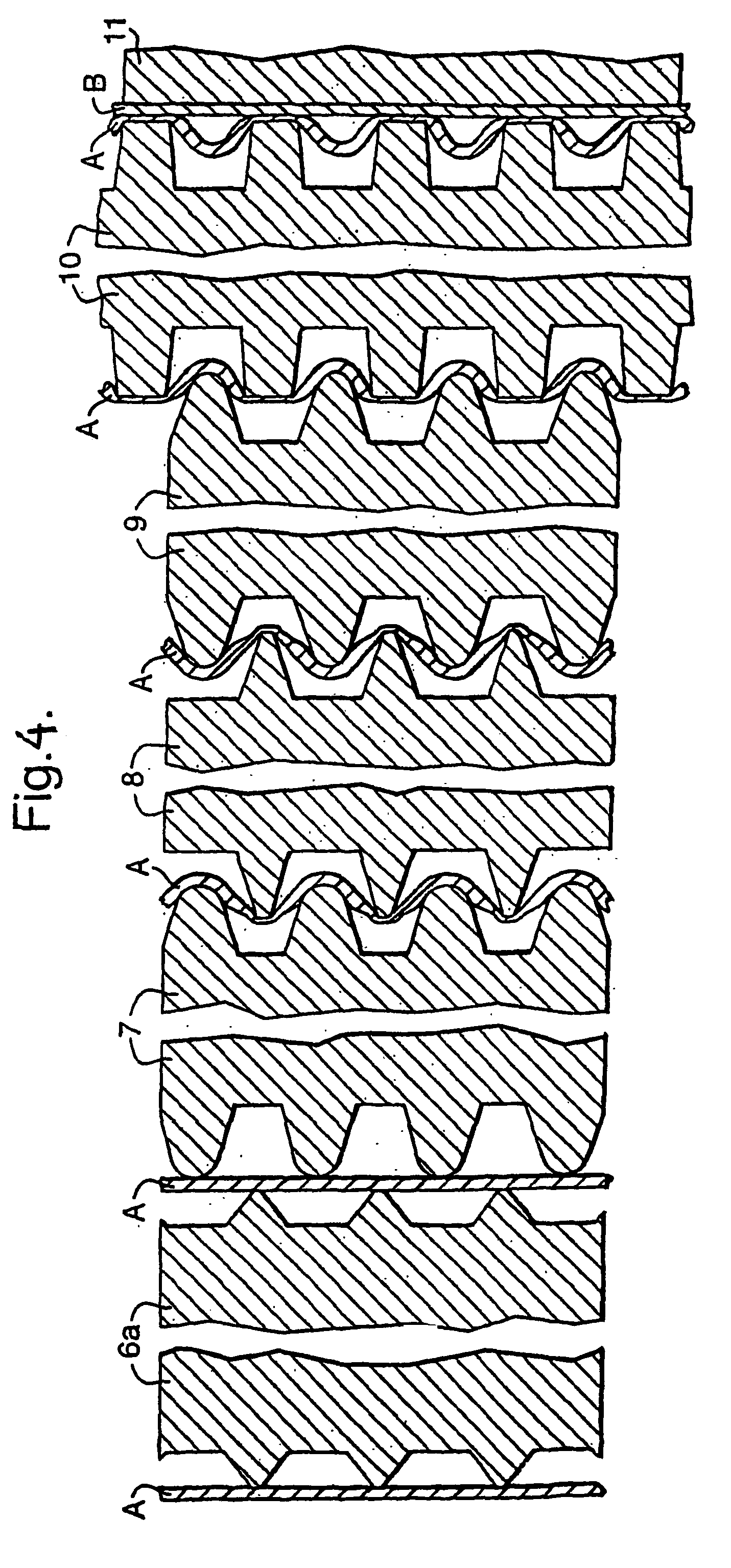
[0154]A 2-ply laminate of ply A and ply B with A longitudinally and B transversely fluted and oriented was manufactured on a pilot unit constructed as shown in FIGS. 4 and 5. Both plies consisted of one coextruded, cold-stretched 0.037 mm thick film consisting of HDPE with a thin layer on one side consisting of an ethylene copolymer having a melting range between 95-105° C. This was used as lamination layer in the process. The cold-stretching was carried out near room temperature at a draw ratio about 3:1 and was followed by heat stabilisation, all by well-known means, and while the film had flat tubular form. The tube was longitudinally cut to form ply A.

[0155]Processes for continuous manufacture of transversely oriented film are well known and mentioned in the foregoing, but it would have caused practical complications for the inventor to have such film manufactured according to his specifications, and therefore short lengths of the ply A-film were heat-sealed together edge to edg...

example 2

[0170]The procedure of example 1 was repeated with the difference that the division of axial grooves on the rubber coated lamination roller is changed from 2.0 mm to 1.0 mm with the land being 0.5 mm. This also produces flutes in B by the shrinkage of A. The height of these flutes is measured to be 0.25 mm.

example 3

[0171]The film produced as explained in example 1 was air-heated to 115° C. while the edges parallel to ply A's flutes were fixed between clamps, which however were set up so that they allowed ply B freely to shrink. Hereby the wavelength in ply A was reduced to 0.8 mm.


PUM

PropertyMeasurementUnit
angleaaaaaaaaaa
angleaaaaaaaaaa
wavelengthsaaaaaaaaaa

Abstract

The present invention relates to a flexible laminate of films of thermoplastic polymer material mainly for applications in which relatively high yield strength and ultimate tensile strength is required, and a method and apparatus for its manufacture. The laminate comprises a monofilm formed or multifilm-formed ply (A) and another monofilm-formed or multifilm formed ply (B) both mainly consisting of orientable thermoplastic polymer material, in which A has a fluted configuration and B on a first side is adhesively bonded in bonding zones to the crests on a first side of A, in which B also has a fluted configuration, the flute direction of B forming an angle from generally about 30° up to and including 90° to the flute direction of A and the said bonding zones being on the crests of the first side of B to produce spot bonding with the crests on the first side of A, the wavelengths of the flutes in A and/or B are no longer than 5 mm, and the wavelengths of the flutes in both A and B are less than 10 mm.

Description

FIELD OF THE INVENTION[0001]The present invention relates to a flexible laminate of films from thermoplastic polymer material mainly for applications in which relatively high yield strength and ultimate tensile strength is required, and a method and apparatus for its manufacture. In special aspect it also relates to film laminates which allow air but not water to penetrate, and laminates with properties as filter material. Examples of applications are: tarpaulins and cover-sheets, pond liners, substitute geotextiles, weather or gas protective garments, greenhouse film, industrial bags or garbage bags, carrier bags, self-standing pouches, and sanitary backsheets.DESCRIPTION OF RELATED ART[0002]For economical reasons there is an increased need to reduce the square meter weight of flexible film made from thermoplastic polymer material. The limits are partly set by the required strength properties, and partly by the required self supporting capability, i.e. stiffness or resilience with ...

Claims


Application Information

Patent Timeline
Patent Type & Authority Patents(United States)
IPC IPC(8): B32B1/00B32B3/12B32B3/28B32B27/14B32B3/20B32B3/30B29C53/28B31F1/22B32BB32B37/14B65D30/08
CPCB29C53/28B32B3/28B32B37/144B65D31/02B31F1/225Y10T428/24744B32B2307/544B32B2307/736Y10T428/193Y10T428/24661Y10T428/24727Y10T428/24562Y10T428/24628Y10T428/24826Y10T428/24694Y10T428/24711B32B2398/20B32B2555/02B32B2323/043B32B2307/54B32B2419/00B32B2439/46B32B27/32B32B27/08B32B2038/047B32B2323/10B32B7/12
Inventor RASMUSSEN, OLE-BENDT
Owner RASMUSSEN OB
Why Eureka
Try Eureka