Ion mobility spectrometer and method for operation

a technology of mobility spectrometer and ion beam, which is applied in the direction of mass spectrometer, separation process, instruments, etc., can solve the problems of not being realistically able to modify the parameters during operation, the inability to detect other analyte substances, etc., to achieve the effect of reducing the amount of analyte substances flowing, avoiding oversaturation, and reducing the concentration

Active Publication Date: 2011-03-08
BRUKER OPTICS GMBH & CO KG
View PDF35 Cites 4 Cited by
  • Summary
  • Abstract
  • Description
  • Claims
  • Application Information

AI Technical Summary

Benefits of technology

A second method reduces the flow of analyte-containing gas into the measuring tube through switchable by-passes. This may reduce the amount of analyte substances flowing through the reaction chamber and may avoid over-saturation. A related method mixes the analyte-containing gas flow with purified gas shortly before entering the reaction chamber, thus diluting the analyte substance and decreasing its concentration.
A third method switches gas flows from two membrane inlets of very different permeability to reduce sensitivity.
A fourth method guides the gas flow inside the reaction chamber on different paths, thus controlling the exposure of analyte substance molecules to protonating reactant ions.
With two or more membrane inlets, sample gas from several sampling locations may be cyclically measured independently from each other without excessive waiting times. As in the first method described above, reversing the flow may help to control over-saturation.

Problems solved by technology

During the dead time, the ion mobility spectrometer is no longer able to perform its warning function nor able to detect other analyte substances.
The dead times caused by excessive analyte substance concentrations in the measuring tube may often be significantly longer than the time required to purge the heated membrane.
It is not realistically possible for these parameters to be modified during operation to match changed measuring conditions.
During the settling time, the ion mobility spectrometer does not yield any reliable results.
The sluggishness of the membrane inlet results in relatively long cycle times which seriously restrict the usefulness of such a method.

Method used


Image

  • Ion mobility spectrometer and method for operation
  • Ion mobility spectrometer and method for operation
  • Ion mobility spectrometer and method for operation

Examples


first embodiment

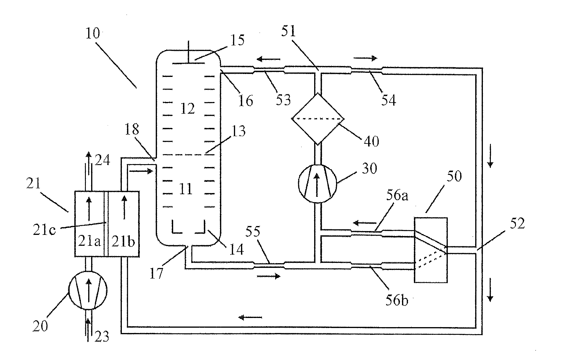
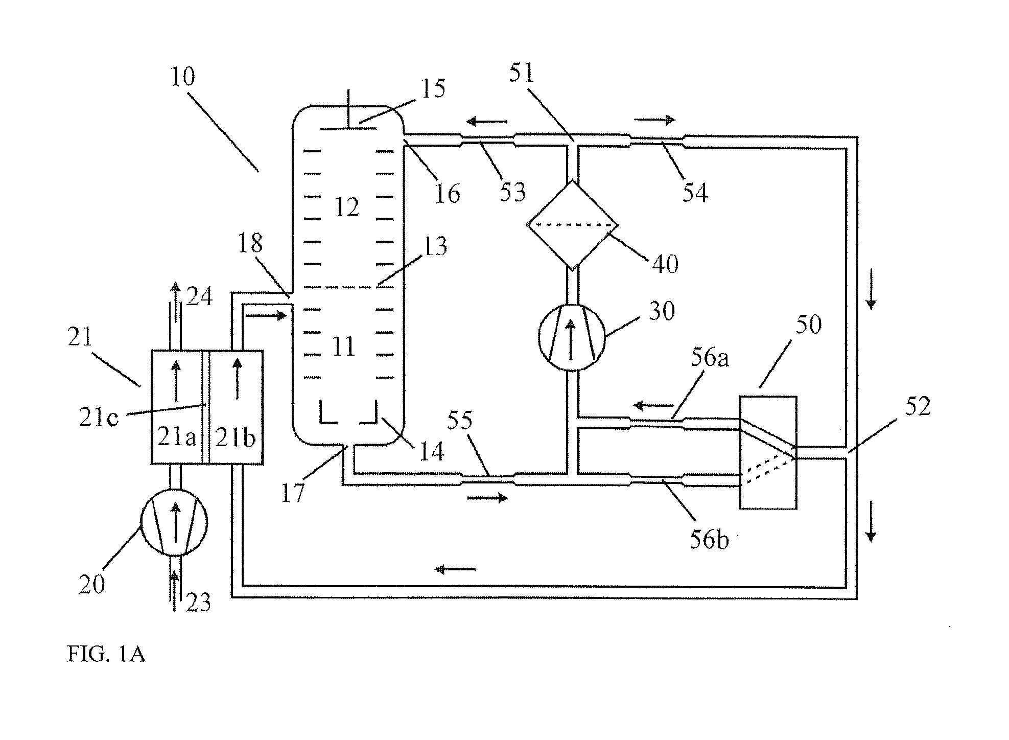
In a first embodiment, to control the quantity of circulating gas with analyte substances that flows into the measuring tube, the flow into the measuring tube periodically reverses by switching valves in a suitably designed internal gas circuit. The periodic reversal constitutes a metering phase and an isolation phase of a measurement method.

FIGS. 1A and 1B illustrate the two phases of the measurement method. Within the ion mobility spectrometer, the circulating gas that has been cleaned in the filter 40 is divided at the branching point 51, flowing partially into the drift chamber 12 and partially into the center connection of the changeover valve 50. Depending on the setting of the changeover valve 50, circulating gas is transported from the center connection back to the gas pump 30 either through the high resistance restriction 56a or the low resistance restriction 56b. Circulating gas is drawn out of the reaction chamber 11 through the gas connection 17 and flows to the gas pump...


PUM

PropertyMeasurementUnit
humidityaaaaaaaaaa
humidityaaaaaaaaaa
ion mobilityaaaaaaaaaa

Abstract

A method for operating an ion mobility spectrometer comprises supplying an analyte substance into a reaction chamber of an ion mobility spectrometer having a closed internal gas circuit and at least one membrane inlet having an inner membrane chamber, changing at least one of flow resistances and gas paths in the closed internal gas circuit, and controlling at least one of a quantity and a concentration of analyte-containing gas flowing from the inner membrane chamber to the reaction chamber.

Description

PRIORITY INFORMATIONThis patent application claims priority from German patent application 10 2007 052 802.9 filed Nov. 6, 2007, which is hereby incorporated by reference.FIELD OF THE INVENTIONThe invention relates to an ion mobility spectrometer.BACKGROUND OF THE INVENTIONPossibly dangerous substances, for example analyte substances, in ambient air are monitored in a large number of applications, such as environmental air analysis in nature or in buildings (e.g., inside chemical companies; for the detection of leaking poisons, chemical warfare agents (CWAs) or explosives). Ion mobility spectrometry is a method introduced in the 1970s for highly sensitive detection of polluting substances at low concentrations in air or other sample gases.An ion mobility spectrometer (IMS) can be operated at ambient pressure. Ion mobility spectrometers are relatively compact and can be manufactured simply and inexpensively, which makes them particularly suitable for portable and mobile gas monitors ...

Claims


Application Information

Patent Timeline
Patent Type & Authority Patents(United States)
IPC IPC(8): H01J49/00B01D59/44
CPCG01N27/622H01J49/0427G01N1/22G01N1/40H01J49/40
Inventor LANDGRAF, JURGEN
Owner BRUKER OPTICS GMBH & CO KG
Why Eureka
Try Eureka