
Submersible turbine-generator unit for ocean and tidal currents

a technology of submerged turbines and generators, which is applied in the direction of electric generator control, liquid fuel engines, machines/engines, etc., can solve the problems of wind resources, view shed issues, and major obstacles to the development of most projects, and achieve the effects of wide market acceptance, greater range of renewable ocean energy resources, and reduced maintenance costs

Active Publication Date: 2011-03-08
OCEAN RENEWABLE POWER COMPANY
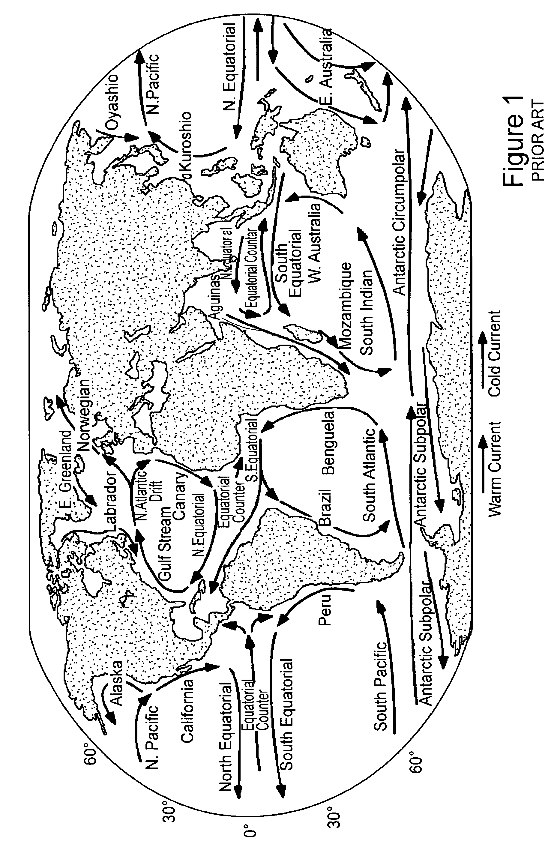
View PDF55 Cites 48 Cited by
  • Summary
  • Abstract
  • Description
  • Claims
  • Application Information

AI Technical Summary

Benefits of technology

These units provide a reliable and efficient means of harnessing ocean and tidal energy, overcoming operational and maintenance challenges, and avoiding adverse impacts on marine life, with the potential for widespread market acceptance and utilization of renewable energy resources.

Problems solved by technology

While wind generation is rapidly expanding and is an important piece of solving the world's energy needs, wind resources are limited, power generated by wind is not predictable and “view shed” and “not-in-my-back-yard” issues restrict development of wind projects.
In fact, view shed issues have become a major obstacle for develop of most projects, regardless of their societal benefits.
Ocean power generation, on the other hand, has essentially unlimited development potential, is predictable, if not constant.
Internationally, the market for renewable energy is virtually unlimited.
Coastal communities throughout the world will be the primary beneficiaries of ocean power due to the presence of strong ocean and tidal currents and insufficient energy supply.
In many areas, electricity is produced by old and inefficient diesel generating plants that are prohibitively expensive and must be subsidized by the state.
Due to the severe terrain, weather and environmental constraints in Alaska, there is no integrated transmission system, which has resulted in the proliferation of nearly 120 public and municipal owned utilities.

Method used


Image

  • Submersible turbine-generator unit for ocean and tidal currents
  • Submersible turbine-generator unit for ocean and tidal currents
  • Submersible turbine-generator unit for ocean and tidal currents

Examples


Embodiment Construction

[0072]Exemplary embodiments of the invention are discussed in detail below. While several specific exemplary embodiments may be discussed, it should be understood that this is done for illustration purposes only. A person skilled in the relevant art will recognize that other components and configurations can be used without departing from the spirit and scope of the invention.

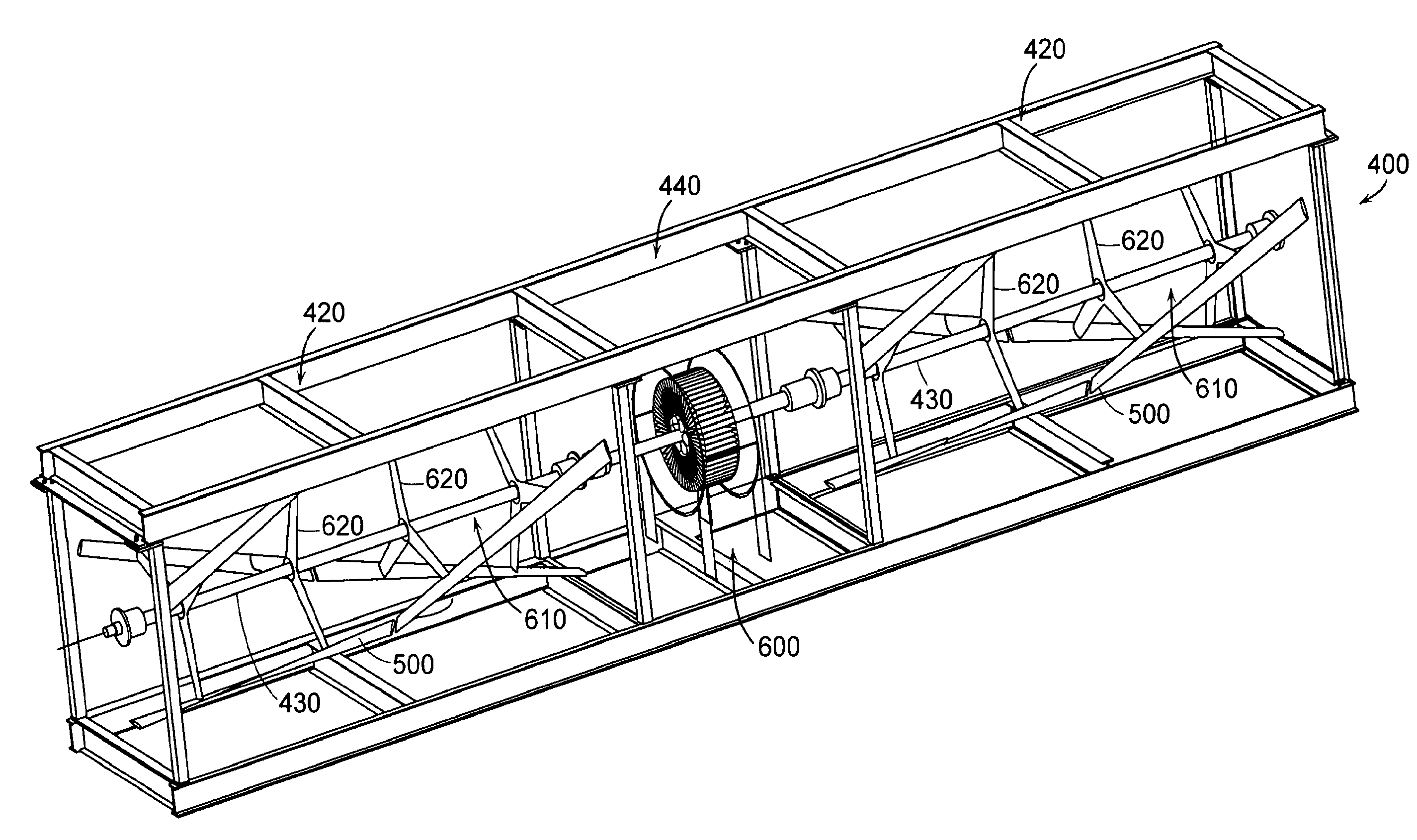
[0073]Referring now to FIGS. 4 and 5, there is shown a submersible turbine-generator unit 400 according to one embodiment of the present invention. turbine-generator unit 400 generally comprises a support structure 410 upon which at least one, and preferably a pair, of turbines 420 are coupled by a single shaft 430 to a generator (not shown in FIGS. 4 and 5) within a pressurized enclosure 440.

[0074]As shown in the CAD projections of FIGS. 6-10, module 400 further comprises unique turbine blades 500 to drive a generator 600. On example of a configuration of turbine blades 500 useful in the present invention is t...


PUM


Abstract

A submersible turbine-generator unit includes two or more turbines mounted on a common shaft with a generator therebetween. Each such turbine is capable of providing relatively low-speed, unidirectional rotation under a reversible ultra low head pressure and / or low velocity fluid flow. A plurality of airfoil-shaped turbine blades mount parallel to the common shaft and transversely to the direction of fluid flow for rotation in a plane parallel to the fluid flow. The turbines convert energy in the waterway currents into mechanical energy that will transfer through the turbine shaft to a cylindrical permanent magnet generator which will convert mechanical energy in the form of RPM and torque into electricity. Electricity from the variable speed electric generator is controlled, synchronized, conditioned and transformed into utility-grade electricity using a power electronics system in each module.

Description

RELATED APPLICATIONS[0001]The present application claims priority to U.S. Provisional Application No. 60 / 853,028 filed on Oct. 20, 2006, the entire content of which is incorporated by reference.BACKGROUND OF THE INVENTION[0002]1. Field of the Invention[0003]The present invention relates generally to sources of renewable energy, and more particularly to a submersible turbine-generator unit for ocean and tidal currents.[0004]2. Related Art[0005]Ocean and tidal currents are capable of providing a virtually inexhaustible supply of emission-free renewable energy. Since ocean and tidal currents exist everywhere in the world and are either constantly flowing or extremely predictable, converting the energy in these currents to electricity could provide a predictable, reliable and, in some cases, base load supply of electricity to the electric power systems or remote sites in many parts of the world. Seventy percent (70%) of the world's population lives within 200 miles of an ocean. Accordin...

Claims


Application Information

Patent Timeline
Patent Type & Authority Patents(United States)
IPC IPC(8): F03B7/00
CPCF03B13/12F03B13/264F03B17/063F05B2220/61Y02E70/10F05B2240/95F05B2280/6003F05C2253/04Y02E10/28F05B2240/40Y02E60/36Y02E10/30Y02E10/20
Inventor SAUER, CHRISTOPHER R.SYVERSON, CHARLES D.MCGINNIS, PATRICK
Owner OCEAN RENEWABLE POWER COMPANY
Learn More