Wires on demand: run-time communication synthesis for reconfigurable computing

a reconfigurable computing and run-time communication technology, applied in the field of reconfigurable computing and reconfiguration of fieldprogrammable gate arrays, can solve the problems of time and energy consumption in recompiling and reconfiguring an fpga, volatile configuration memory of an fpga, and loss of fpga functionality

Inactive Publication Date: 2011-03-08
LUNA INNOVATIONS +1
View PDF1 Cites 46 Cited by
  • Summary
  • Abstract
  • Description
  • Claims
  • Application Information

AI Technical Summary

Benefits of technology

[0012]It is therefore an object of the present invention to provide a module-based RTR of FPGAs. Another object is to provide a flexible allocation of logic and wires from a dynamic pool and run-time adaptable point-to-point communication. It is also an object of the present invention to leverage existing design methodologies and tools and focus on streaming applications.

Problems solved by technology

However, the configuration memory of an FPGA is volatile and must be configured every time the power is up.
When the power is down or off, the FPGA loses its functionality.
Moreover, recompiling and reconfiguration of an FPGA is time and energy consuming.
A disadvantage is that the full bitstreams cannot be downloaded on the fly and the operation of an FPGA may have to stop prior to receiving new full bitstreams.
Even if such objectives are achieved, the significant increase in design effort works against the main attraction of FPGA technology.
This degree of abstraction is sorely missing for RTR application development.
Its commercial failure resulted from, among other things, poor support for reconfiguration in the associated tools, and a lack of architectural features (such as fast arithmetic) that designers were accustomed to.
However, most designers were not willing to forgo the Register Transfer Level (RTL) design abstraction with familiar Hardware Description Language (HDL) and timing-driven implementation tools.
In addition to the manual effort required to insert and place the bus macros, a number of limitations arise due to the lack of a run-time environment.
The constraints of this static approach result in the same inflexibility or resource waste as static array allocation in programs.

Method used


Image

  • Wires on demand: run-time communication synthesis for reconfigurable computing
  • Wires on demand: run-time communication synthesis for reconfigurable computing
  • Wires on demand: run-time communication synthesis for reconfigurable computing

Examples


Embodiment Construction

[0026]Preferred embodiments of the invention will be set forth in detail with reference to the drawings, in which like reference numerals refer to like elements or steps throughout.

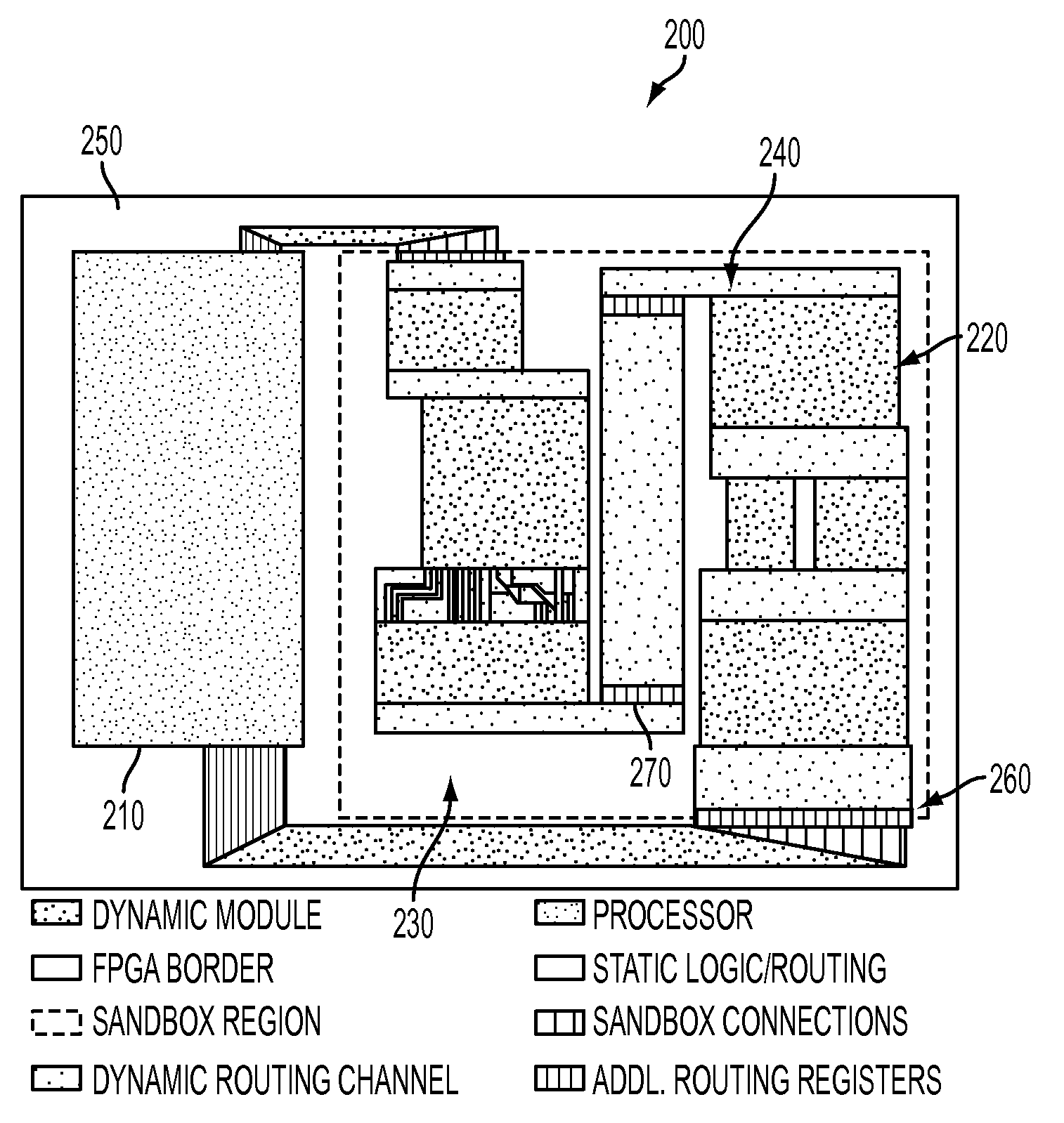
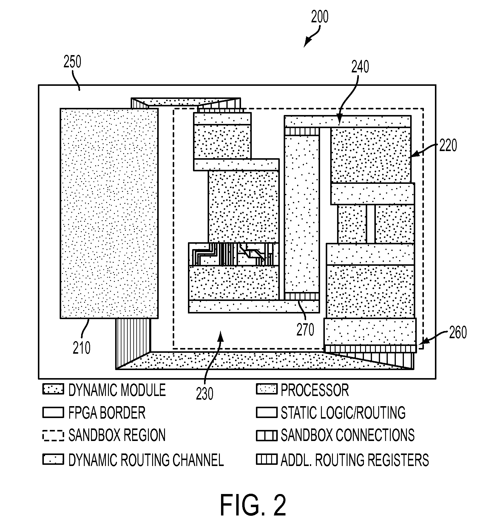
[0027]The present invention divides the reconfiguration of an FPGA into two main steps: (1) creating a dynamic module library during compile-time operations (preprocessing dynamically instantiated IP) and (2) computing the reconfiguration external to the FPGA during run-time operations (placing modules and completing connections). After the reconfiguration is computed, the system sends partial bitstreams that represent the reconfiguration function to the FPGA. The FPGA contains a basic, static region and a dynamic region. The dynamic region is also called a sandbox where, as explained below, logic modules are reconfigured, placed and interconnected during run-time operations.

[0028]The dynamic module library may be created during compile time. The library is composed of preprocessed IP blocks, stored in th...


PUM


Abstract

A method, and system, for reconfiguring an FPGA which has a static region and a dynamic region is provided. The method includes the steps of: (a) providing a dynamic module library having information of predetermined modules; (b) receiving a reconfiguration request external to the FPGA; (c) computing reconfiguration of the FPGA at a predetermined location using predetermined module information from the dynamic module library and the reconfiguration request, and generating reconfigurable partial bitstreams; and (d) sending partial bitstreams from the predetermined location to the FPGA to perform the reconfiguration.

Description

REFERENCE TO RELATED APPLICATIONS[0001]The present application claims the benefit of U.S. Provisional Application No. 60 / 968,091, filed Aug. 27, 2007, whose disclosure is hereby incorporated by reference in its entirety into the present application.[0002]The present application is also related to U.S. Provisional Application No. 61 / 084,429, filed Jul. 29, 2008.STATEMENT OF GOVERNMENT INTEREST[0003]The work leading up to the present invention was supported by United States Air Force Contract No. FA8651-06-C-0126. The government has certain rights in the invention.FIELD OF THE INVENTION[0004]The present invention is directed to field-programmable gate arrays (FPGAs), and more particularly to a method and system for configuration and reconfiguration of FPGAs during run time operations.DESCRIPTION OF RELATED ART[0005]FPGAs are first introduced by Xilinx, Inc. in 1985. FPGAs are semiconductor devices that can be programmed and reprogrammed to perform logic functions. Each FPGA contains h...

Claims


Application Information

Patent Timeline
Patent Type & Authority Patents(United States)
IPC IPC(8): H03K19/177
CPCG06F17/5054G06F30/34
Inventor PATTERSON, CAMERONATHANAS, PETERBOWEN, JOHN K.DUNHAM, TIMOTHY G.RICE, JUSTIN D.SHELBURNE, MATTHEW T.PLETRI, JORGE A. SURISGRAF, JONATHAN
Owner LUNA INNOVATIONS
Why Eureka
Try Eureka